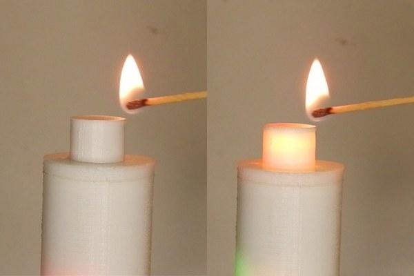
Hello again, everyone. In this Instructable, you will see something really cool and exciting and you might not have seen such a thing yet on the internet. We will design and make a 3D printed artificial candle. But the interesting part of our project is that it will not be ignited using some switch but it will be ignited using the flame of a real matchstick or lighter, just like an ordinary candle.
When we bring a flame from a matchstick or lighter near the top tip of our artificial candle, the LED bulbs present at the top of the artificial candle will magically light up. There’s also another interesting element in our project. This is going to one no ordinary artificial candle but it will be an artificial candle that flickers too!
Sounds interesting? Let’s dive in further to know how we will go about doing all of this!
Subscribe to Tech Nuttiez for more updates!
Supplies
The stuff you will need for this project:
Components:
- Arduino Nano
- Flame Sensor
- 2 x Yellow LEDs
- 1 x Red LED
- CR2032 Coin Cell 3V
- Coin Cell Holder
- Toggle Mini Switch
My choice for all components: Quartz Components
Tools (Optional):
- Soldering Iron
- Hot Glue Gun
- 3D Printer / 3D Printing Service (My Choice: IAmRapid)
After gathering all the required things, move ahead to the next step!
Step 1: Concept + Features
There are two main features in our artificial candle that set it apart from any other artificial candle out there:
1.1 Ignited Using Real Flame:
The most important feature of this 3D printed artificial candle is that it does not switch on using a remote or a switch on the candle. But, it switches on and starts glowing when a real flame of a matchstick, lighter etc. is brought closer to the top tip of the candle. The trick here is really simple. We just have a flame sensor at the top of the candle which is present in a very minimalistic form factor so as to be almost hidden from everyone.
This flame sensor senses any kind of flame brought near it and gives a signal to the Arduino Nano board inside the candle to turn on the LEDs of the candle and in this way it starts glowing after being triggered by a real flame.
1.2 Flickering Candle
This is a feature that you might have seen in a few artificial candles, unlike the previous feature. For this to happen we are going to be using 3 LEDs instead of just one and they are going to be in yellow (2) and red (1). The LEDs will glow and go off in a pattern one after another so as to create the whole flickering effect that we are talking about. The flickering feature was inspired by TheArduinoGuy from this Instructable!
These features will make our artificial candle look almost real in all ways.
Replaceable Battery
As we are making a candle that needs to keep moving from one place to another in our house. And also, it is not a great idea to always have a wire connected to a candle, especially when we are trying our best to make it realistic. For this, I have added a small 3V coin cell with its required battery holder, to the project. I’ve also added a small slide switch at the bottom of the candle, to help us turn the whole circuit on and off. We can probably completely eliminate this switch in the upcoming versions of this project where we might blow on the candle to turn it off. But, in this version, the candle will have to be manually turned off.
Step 2: Circuit Diagram / Wiring
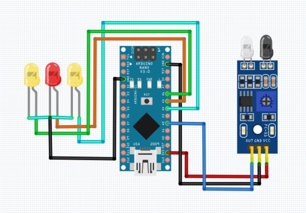
The circuit diagram and wiring of this project are very simple because it has a very less number of components. The major components involved in the wiring are:
- Arduino Nano Board
- IR Flame Sensor
- Three LEDs
Note: The IR sensor used in the above circuit diagram represents the IR flame sensor. I did not get the exact flame sensor in the library of components and thus used this sensor instead for demonstration purposes. The pinout and wiring remain the same for the flame sensor.
You can follow the circuit diagram present above to build the circuit very easily. There is also no need of soldering anything in this circuit and you can get your way out even without a soldering iron.
I have not added the battery to the circuit as that is pretty obvious and you can go about adding it yourself quite easily. Also, the switch must be added in between the Arduino and the battery.
After completing the circuit move ahead onto the next step!
Step 3: 3D Design (Tinkercad)
Now, we need to design the body of our candle for it to be 3D printed. I designed the candle in Tinkercad.
3.1 The Design
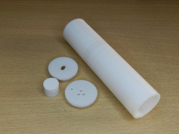
There are four parts in the body of our candle:
- Main Cylinder
- Bottom Piece
- Top Piece
- Flame Cover
The main cylinder is a hollow cylinder that will also act as a housing for the electronic components of the candle, alongside acting as the body of the candle.
The top and bottom pieces are designed to be snap-fit on the top and bottom of the main cylinder. The bottom piece has a small rectangular opening for the USB port of the Arduino Nano board. The top piece has four small holes in it – three for the LEDs, one for the flame sensor’s IR receiver diode.
The flame cover will act as a small cap on all of the three LEDs so that their glow looks merged together to get a better-looking diffused glow. The flame cover will be 3D printed in white and will have very thin walls so as to be translucent and amplify the glow tremendously giving an aesthetic effect to the candle.
3.2 3D Printing the Candle
Now that we are done with the design, we can go on and 3D print our design. You can use any 3D printer for the same. If you do not have one, you can get it 3D printed from a 3D printing service. I got the parts of my candle printed from IAmRapid. They have an amazing service and fabulous product quality and delivered the parts to me within two days (in India).
After you have all the 3D printed parts with you, you can move on to assembling everything!
Step 4: Working With the Top Piece
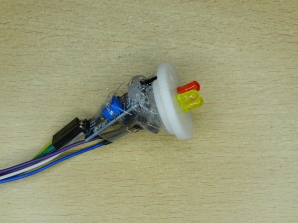
We have the circuit diagram. We also have the 3D printed parts for the candle by now. Now, we need to put together everything so that the candle works.
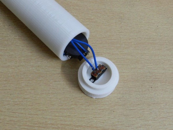
There are three holes for the three LEDs on the top piece of the candle. The LEDs need to be inserted into these holes (in no particular order). There is also a hole for the flame sensor’s IR diode. The diode can be half inserted in the hole and then fixed on the backside using some glue or anything suitable.
The wires from the LEDs and the flame sensor can be connected to the Arduino Nano board now and doing this will complete the circuit for us. Now just insert the Arduino board along with the whole circuitry and wires into the body of the candle. Now you can snap-fit the top piece onto the candle’s main cylinder.
After completing the assembly of the top piece, move on to the next step!
Step 5: The Bottom Piece Now
Now, we come over to the bottom piece. The bottom piece has a small rectangular opening to accommodate the small slider of our mini DPDT switch that enables the electricity flow from the battery to the Arduino Nano board.
I did not use a huge rocker switch but went for this as this saved space and was easier to work with. You can now insert the slider of the switch from the inside of the bottom piece, aligning it such that the slider can properly be moved from the outside.
Make sure to fix the slider switch perfectly in place from the inside using tons of hot glue (or any other method) so that the switch doesn’t get detached and start moving when we slide it from the outside. There will be a little pressure on the switch that it needs to bear to stay alive.
After completing the assembly of the bottom piece, move on to the next step!
Step 6: Finishing Assembly – Flame Cover

Now, we are almost done with the assembly of our candle. We are done with the top and bottom pieces. Now we can go ahead and add the flame cover on the top of our three LEDs so that when they glow, this cover causes a diffused and mixed glow effect along with a flickering candle effect.
Without the flame cover, the LEDs would look rough and would not be able to give a smooth and merged look that a real candle has and the one which we want.
After completing the assembly move on to the next step!
Step 7: Coding Showdown

Now, we are done with the assembly of our artificial candle. We just need to make our candle functional. For that, we obviously need to write code and flash it to the Arduino Nano board present inside our candle. You can write the code for this project very easily by yourself, or use the code given by me here:
////////////////////////////////////////////////////////
  //              Realistic Artificial Candle           //
 //              By Aarav Garg - Tech Nuttiez          //
////////////////////////////////////////////////////////

#define flamePin A7
#define ledPin1 A0
#define ledPin2 A2
#define ledPin3 A5

int state = 0;

void setup() {
  // put your setup code here, to run once:
  pinMode(flamePin, INPUT);
  pinMode(ledPin1, OUTPUT);
  pinMode(ledPin2, OUTPUT);
  pinMode(ledPin3, OUTPUT);
  Serial.begin(9600);
  state = 0;

}

void loop() {
  // put your main code here, to run repeatedly:
  Serial.println(analogRead(flamePin));
  if (analogRead(flamePin) < 500){
    state = 1;
  }
  if (state == 1){
    analogWrite(ledPin1, random(50)+125);
    analogWrite(ledPin2, random(50)+115);
    analogWrite(ledPin3, random(50)+135);
    delay(random(100));
  }

}
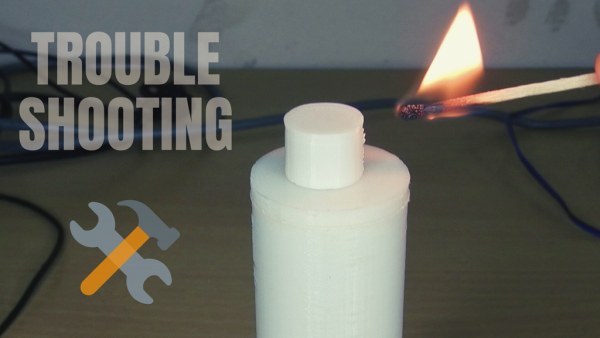
Step 8: And Here We Go!

Here we have our working realistic artificial candle that does not turn on by pressing a switch or using a remote, but it turns on and starts glowing when the flame of a real matchstick or a lighter is brought near the top tip of this candle. You can use it as a decorative item in your house and show off the lighting feature to guests
You can also use the same flame sensor to almost light any other shaped lamp or light as well. You can also use different coloured LEDs other than the ones which I used according to your need or wish.
I enjoyed making this a lot as this was a great design challenge as well as a very interesting concept to work on!
Step 9: Troubleshooting
If you are here, then I assume that you have built the project and it either worked which is great or it didn’t which is also great because you not only will know how you build something but also how you do not build it and this kind of learning is very useful.
9.1 It Did Not Work :
- 9.1.1 Parts Not Snap-Fitting: In this case, there was a slight error in the 3D print, very minor though. For this, you can just sand the edges of both the pieces and try to fit them again and repeat this till it works.
- 9.1.2 All LEDs Not Glowing: In this scenario, the issue is mostly going to be with the Flame Sensor. Try checking if the small green LED on the flame sensor is responding to flame or not. If the flame sensor is OK, then either all of your LEDs are fused or there is an issue with the code.
- 9.1.3 Some LEDs Not Glowing: If there is this issue, then that’s mostly with the LED and this means that the LED that is not working is most probably fused. In the worst case, there can even be an issue with the coding part of some LEDs in particular.
9.2 It Worked :
Great job mate. You overcome all the obstacles and finally are here, touching victory yourself and that is amazing. There is also a section down here “I Made It”. Meet me there.
Step 10: What Lies Ahead!
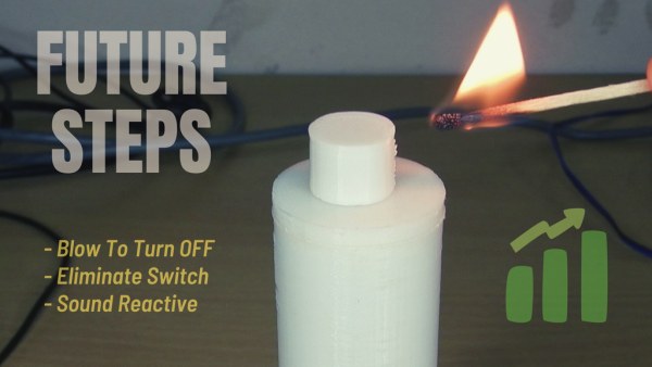
This was a really fun project to work on and I wish to add on features to this while keeping everything still minimal in form factor. A very interesting feature can be added to this project in the future and that is the candle getting extinguished or turning off when we blow at the top tip of the candle.
This feature will take a lot of effort I think but is still possible to be implemented. Stay tuned to get all these updates. Subscribe to Tech Nuttiez for more updates!
Source: Artificial Candle Ignited by Real Flame