Summary of Armadino – an Arduino Gameboy, Clock, Electronic Lab, TVout Console and More…
Armadino is a compact Arduino-UNO–compatible handheld styled like a Gameboy featuring a 10x8 dual-color (red/green) LED matrix, dual 7-segment display, buzzer, buttons, I2C and I/O breakouts. It uses an ATmega328 MCU, a 16-bit constant-current LED driver and a 4017 decade counter to multiplex a larger matrix, refreshed via an ISR-driven library supporting graphics, text, tones, buttons, TVout, and example games (Snake, Space Invaders, Pong) and a clock using an RTC. The project includes PCB design, assembly steps, and plans for a GitHub repo.
Parts used in the Armadino:
- AVR ATmega328 micro controller
- MacroBlock 5026 16-bit constant-current sink LED driver
- 4017 decade counter, DIP
- LED Matrix, 5x8, Red-Green, Common-anode (x2)
- 7-segment LED (x2)
- buzzer or similar
- PN2222 NPN transistors (x10)
- large tactile switch Omron B3F-4000 or similar (x6)
- small tactile switch Omron B3F-1000 or similar (x1)
- 3-pin ceramic resonator, 16 MHz
- 100nF capacitors (x6)
- 100uF electrolytic capacitor
- 6-pin USB-C connector
- 10k Ohm resistor
- 1.2k Ohm resistor
- 5.1k Ohm resistors (x2)
- right-angle pin strip, 2.54mm pitch
- 8-pin header, 2.54mm pitch (x2)
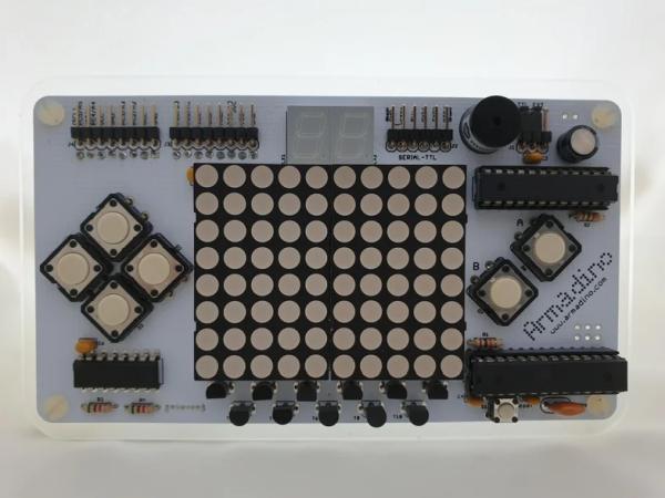
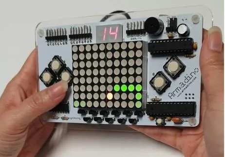
Some years ago, I came across Mignon and Meggy Jr RGB, and was intrigued enough to want to make something similar, but with a wider screen, more possibilities for experiment and play, and with few parts. I called it Armadino, after seeing an armadillo logo on the spine of a children story book and mixing it with the word Arduino. Styled like a Gameboy, Armadino has an 10×8 dual-color (reg and green) LED dot matrix screen, a 7-segment LED “score board”, buzzer, and I2C and I/O breakout pins to play with. Programmable as an Arduino UNO, the Armadino software library includes functions for drawing on the LED matrix and 7-segment display, printing text on them, making tone, sensing buttons, and even working alongside the TVout library!
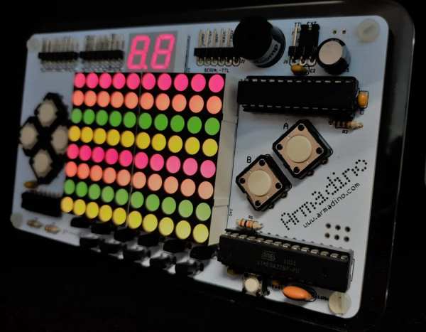
I use it as a LED clock most of the time. Occasionally, I have fun with it with handheld games like the classic Snake, Space Invaders, Pong. I have also adapted some TVout games including Space Invaders, Breakout and Tetris. Visit https://www.instagram.com/armadino.clock/ for short video clips of the clock, handheld and TVout games that are featured here.
Supplies
1 x AVR ATmega328 micro controller
1 x MacroBlock 5026 16-bit constant-current sink LED driver
2 x LED Matrix, 5×8, Red-Green, Common-anode
2 x 7-segment LED
1 x buzzer or similar
10 x PN2222 NPN transistors
6 x large tactile switch (Omron B3F-4000 or similar)
1 x small tactile switch (Omron B3F-1000 or similar)
1 x 3-pin ceramic resonator, 16 Mhz
6 x 100nF capacitors
1 x 100uF electrolytic capacitor
1 x 10k Ohm
1 x 1.2k Ohm
2 x 5.1k Ohm
1 strip of right-angle pin. 2.54mm pitch
2 x 8-pin header, 2.54mm pitch
Step 1: Breadboard Prototype
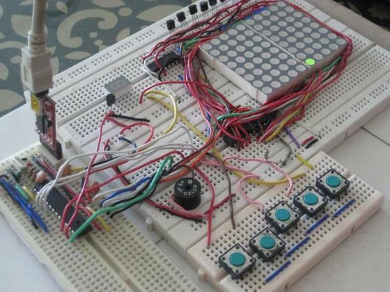
By electing to have 2-colour LED matrix, I could get away with just one 16-bit LED driver to make a larger 10×8 matrix (instead of the usual 8×8) by laying two 5×8 matrix next to each other; and added a pair of 7-segment LEDs as a scoreboard. The palette of colour mix (red, green, orange, yellow) is sufficient to do interesting things on a 10×8 matrix.
For each column, the red and green colour dots (8 rows x 2 colours) are shifted into the 16-bit LED driver. The column is then turned on by a NPN transisitor as an emitter follower through the 4017 decade counter. And each sweep from column 1 to 10 has to be done very rapidly, at about 1000 Hz. This is fast enough that by selectively not turning on a particular dot, we could vary the brightness of that dot.
Step 2: Software Library
Meggy Jr RGB more than inspired the hardware design. I learned from it how an interrupt service routine (ISR) is used to refresh and modulate the brightness of the LED matrix with the constant-current LED driver; and how to ease button handling in the library. I made a small improvement to debounce the buttons.
For generating the buzzer tone using Phase and Frequency Correct PWM (pulse width modulation), I turned to Ronald Willem Besinger’s blog “AVR Twinkle Twinkle Using PWM Project”
I am sorry that I have not been able to upload the Armadino library for Arduino as a .ZIP file nor the EagleCAD .brd file in Step 3. Perhaps I should make a GitHub Repo for this project instead and hope to do so very soon, see step 14.
Step 3: Design the PCB
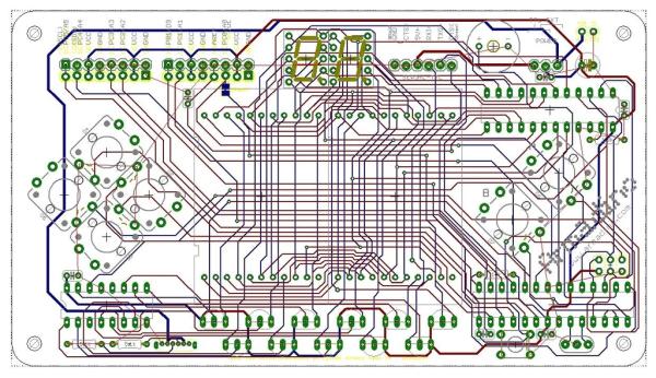
The PCB was designed with a rather dated v5.7 of EagleCAD. For it to look good, care was taken to layout the components with some degree of symmetry and route the traces such that all vias are hidden behind components.
Step 4: Assemble the PCB, Starting With Power Supply
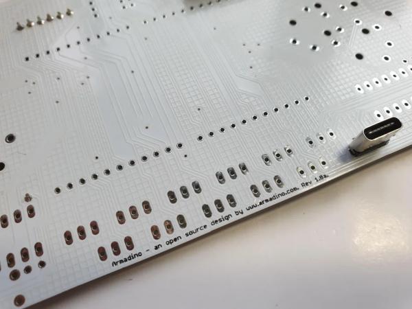
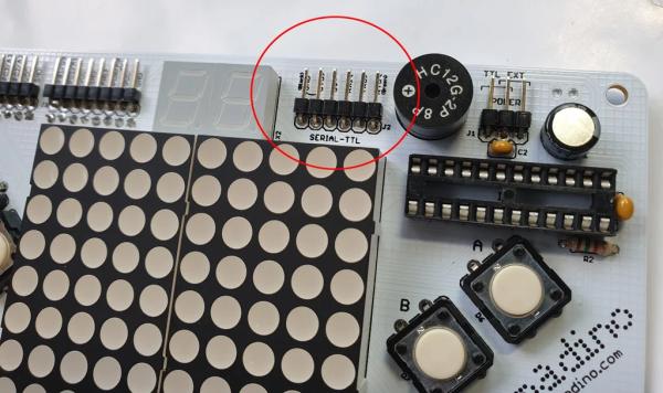
To begin with, solder the 6-pin USB-C connector on the back of the PCB. Armadino may be powered in two ways: from the 5V pin of the serial-TTL programming interface, or this USB-C connector. This is selected with a jumper switch located at its top right corner.
Step 5: Pinouts and Headers
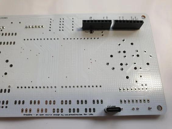
Next are the series of pinouts so that Armadino can be interfaced with sensors or even another Armadino (over the serial interface). The headers at the back mirrors the pinouts in front, and are placed such that they are alight with a mini breadboard (see picture in Step 10).
Step 6: Other Components
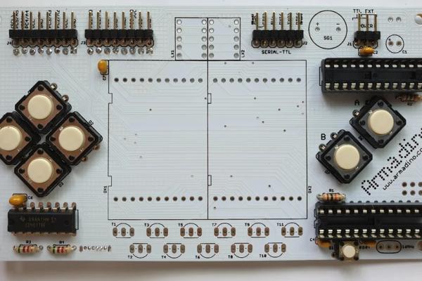
Soldering the remaining components is straight forward, in this order:
- Decouling capacitors
- Tactile switches
- Resistors
- Sockets for ICs
- Transistors
- LED Matrix
- 7-Segment LED
- Buzzer
- Electrolytic capacitor
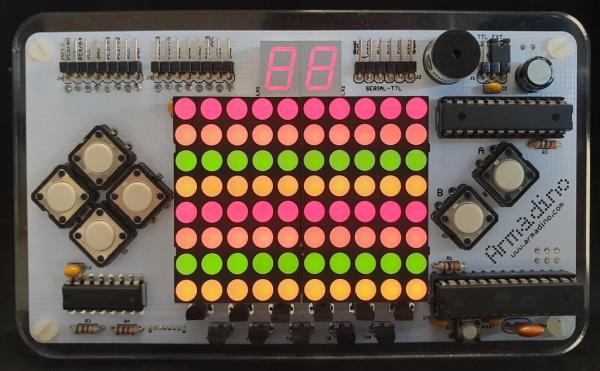
The two tactile switches on the right are labelled A and B.
Step 7: Attaching the Acrylic Base
The PCB is then attached to an acrylic base with 4 plastic screws with extra nuts to act as spacer. There is a 0.6cm hole in the lower centre of the acrylic board to hold a short acrylic rod. This way, the Armadino can stand on its own, and that’s how I get to use it as a clock.
The outline and cutout of the acrylic board is in Layer 248 (Housing) of the EagleCAD .brd file.
Step 8: Set Up Arduino IDE for the Armadino
Programming the Armadino is no different from an Arduino UNO – treat it like an Arduino UNO in a different layout and form factor.
- First unzip the Armadino files into the Arduino libraries folder:
- Armadino library
- Armadino.cpp, Armadino.h, led_refresh.inc, char_set.inc. These are code files that implement the core functions of the library to draw on the LED matrix and 7-segment display, print text on them, making tone, sensing buttons, and working alongside the TVout library.
- armadino_setup.h. This is where some changes can be made concerning Armadino’s bahaviour, the two main ones being whether the buzzer tone should be software driven, and if the TVout library will be used. See the comments in the file for more details.
- examples folder. There are programs for a clock, some games and a separate folder for TVout games. More details are available in later sections of this Instructable.
- TVout and TVfonts libraries. Some minor modifications to the TVout library are required, see the comments in armadino_setup.h. For convenience, I have made these changes and included the TVout folders in the zipped package.
- Attached a USB to serial breakout to the Armadino’s serial-TTL pinouts. 5V is needed, and there are many options from Sparkfun and alternatives: https://www.sparkfun.com/products/9716, https://www.sparkfun.com/products/15096. They typically use a FTDI’s FT232 or WCH’s CH340 chip, and has a jumper on the back of the board that allows the board to be configured to either 3.3V or 5V.
- Install the serial driver if you are prompted to.
- Launch Arduino, select Arduino UNO and the comm port assigned to the USB-serial breakout, and we are set to go.
Step 9: Programming the Armadino: Snake and Space Invaders Game
Let’s use the classic Snake game to get an overview of how to programming the Armadino (refer to the code in Snake.ino, in the examples folder of the Armadino library). Broadly, after setting up the dot matrix and 7-segment bitmaps, the loop polls whether a button has been hit and carries out the action accordingly.
- (line 12) Define an Armadino instance, rmdn, and (line 13 & 14) LedMatrix and Led7Seg instances, m & s respectively, to hold the bitmaps for the dot matrix and 7-segment “score board”.
- (line 23) In setup(), call rmdn.begin() to setup the Armadino hardware and interrupt service routines.
- (line 24,25) get rmdn to display m and s instances by calling rmdn.show().
- (line 45), poll the buttons state with rmdn.checkButtonsPress().
- (line 46-57), carries out the button actions.
The snake isn’t complicated to animate, as the body (made up of a sequence of dots) only needs to follow the head. Thus, each dot takes the place of the proceeding dot as the head moves in the direction according to the button pressed. The snake grow in length as it crosses a “food” dot (line 94), which is ramdonly placed (line 100).
The Space Invaders, Invaders.ino, is arguably more complicated than the Snake game. The novelty lies in how sparse the LED matrix is. While brutal simplification and some imagination are needed to make a game, the programming is not overbearing and quite satisfying.
Step 10: Using the Armadino As a Electronic Kit
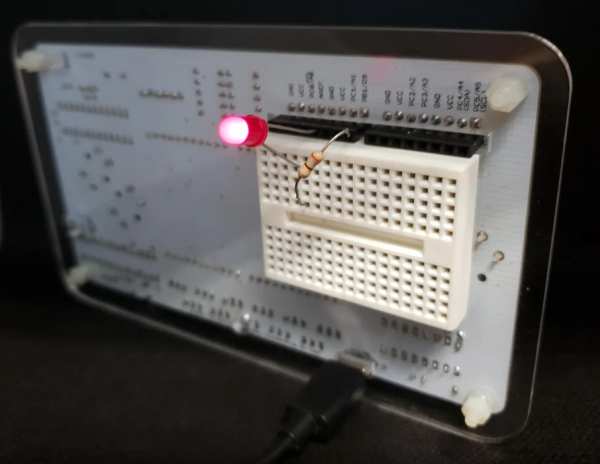
By attaching a mini breadboard on its back, Armadino can be used as a self-contained electronic kit, with an integral standing LED display. The mini breadboard is aligned to the two 8-pin headers.
Whether for experimental or educational purpose, it is always more fun to have an upright color display to visibly show what has been made. For this, I made a LED clock…
Step 11: The Armadino Clock
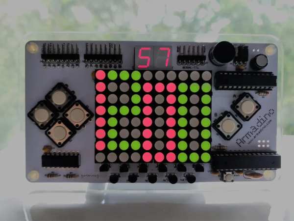
Thankfully, the Armadino breaks out the I2C pins of the ATmega328 controllor and the 10-column matrix is just enough to display a 12-hour time. For the clock, a battery-powered real time clock (RTC) module is required. I adapted a PCB design of a RTC (based on the DS1307 from Maxim Intergrated) breakout from Adafruit, and added a temperature sensor (TMP36) and a simple LDR light sensor. This breakout mounts nicely onto the header at the back of Armadino such that the time and date are read off the I2C pins (with Arduino’s RTClib library), and the temperature and LDR resistance are on analog pins A2 and A3. Pressing the A button will display the date, in a scrolling text.
To complete the Clock.ino program, I added an alarm clock function and a feature to dim the LED matrix display when the ambience is dark as sensed by the LDR.
Step 12: Turning Armadino Into a TVout Game Console
Could I get Armadino to dipslay both the LED dot matrix and TVout at the same time, like a Wii perhaps? This involves a bit of compromise and re-write, chief among which is to intersperse the dot matrix refresh by hooking into the TVout ‘s ISR. Consequently, brightness control for the dot matrix is not possible, and the buzzer will be software-driven and without volumn control.
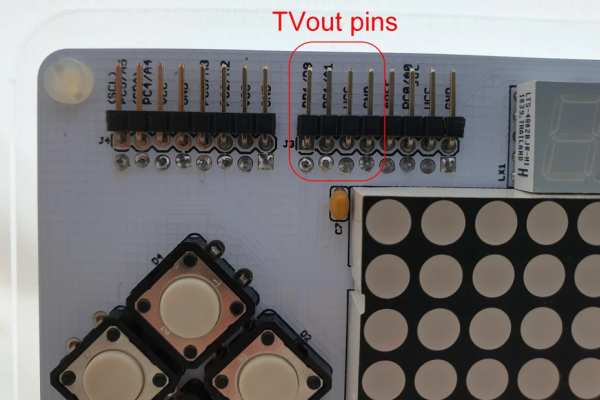
To generate the composite video signal, the TVout library drives pins PB1 (Arduino’s D9) and PC1 (A1) though a 1000 ohm and 470 ohm resistor respectively. See the circuit diagram in armadino_setup.h.
An easy way to make this circuit is to use a Dupont 4-way Cable Plug so that it can sit in the corresponding right-angled pins on the Armadino.
Hackvision from nootropicdesign.com is a TVout game console that is very well-designed and compact, for which a number of games have been written. I have downloaded Space Invaders, Breakout and Tetris and adapted them for the Armadino. They may be found in the examples/TVout subfolder of the Armadino library.
Step 13: May I See the Menu Please?
A convenient way to combine a few programs into Armadino is to present a menu. In the Menu.ino example, the clock and the games Snake and Pong are presented as item in a list which is scrolled through with the Up and Down keys. Hitting the A key will enter that option.
Step 14: Github Repository
What’s left is to create a GitHub Repo to hold the EagleCAD files (both .sch and .brd files) and the Armadino library for Arduino. Meanwhile, visit https://www.instagram.com/armadino.clock/ for short video clips of the clock, handheld and TVout games that are featured here.
Source: Armadino – an Arduino Gameboy, Clock, Electronic Lab, TVout Console and More…
- What microcontroller does Armadino use?
It uses an AVR ATmega328 micro controller. - How is the 10x8 LED matrix driven?
Two 5x8 red-green matrices are shifted into a MacroBlock 5026 16-bit LED driver per column, with columns enabled via PN2222 transistors and a 4017 decade counter, refreshed about 1000 Hz. - Can Armadino be programmed with the Arduino IDE?
Yes; treat Armadino like an Arduino UNO, install the Armadino library and examples into the Arduino libraries folder, and use a USB-serial breakout to program it. - Does Armadino support TVout?
Yes; the Armadino library can work alongside the TVout library and examples for TVout games are included in the examples/TVout folder. - What components are used for sound generation?
A buzzer is used and tones are generated using PWM; the library can drive the buzzer via Phase and Frequency Correct PWM or software-driven methods when TVout is used. - How are buttons debounced?
The Armadino software library includes button handling with a small improvement to debounce the buttons. - Can Armadino function as a clock?
Yes; by using an I2C RTC module (DS1307 based in the project) mounted on the header, plus optional TMP36 and LDR sensors, Clock.ino displays time, date, temperature, and dims the display in dark. - Is the Armadino PCB design available?
The PCB was designed in EagleCAD v5.7; the author plans to create a GitHub repo to host the Eagle files and library but had not uploaded them at the time of writing. - How is the Armadino used as an electronic kit?
A mini breadboard can be attached to the back aligned with two 8-pin headers so the device serves as a self-contained kit with an upright color display. - What games are provided as examples?
Examples include Snake, Space Invaders, Pong, and adapted TVout games such as Space Invaders, Breakout and Tetris.