Summary of Arduino Wii nunchuck and Wii motion plus with updated code for IDE 1.0.2 and LEDs
This article details a DIY project to interface a Wii Nunchuck and Wii Motion Plus with an Arduino to control motors and lights. The author addresses connection challenges by utilizing the Wii Motion Plus's exposed pins and updates outdated code for compatibility with newer Arduino IDE versions. The setup involves wiring the controllers to an Arduino, configuring LEDs based on motion data (yaw, pitch, roll), and modifying system files to ensure proper I2C communication.
Parts used in the Arduino Wii Nunchuck and Motion Plus Project:
- 1 Arduino
- 1 Breadboard
- 1 Wii motion Plus
- 1 Wii Nunchuck
- 6 Resistors 220 ohm
- 6 Leds (any color)
- Solid core jumper wires
So, I was trying to hack my Wii nunchuck because I want to control motors and lights with the Wii nunchuck.
The first problem that I found was how to connect the control without an adapter, I was planning to make one, but
when I was searching for the nunchuck I also found the Wii motion plus accesory then I did notice that it haves a
Male interface it haves holes to put wires, I did a search for Wii motion hacks with arduino and I found some code.
Second problem I found was that the code to hack both nunchuck and wii motion plus are outdated and you have
to change some commands, like Serial.begin, Wire.write instead of Wire.send etc,
So I had to fix the code and also I added leds!
Step 1: Materials
1 Arduino
1 Breadboard
1 Wii motion Plus
1 Wii Nunchuck
6 Resistors 220 ohm
6 Leds (any color)
Solid core jumper wires
Step 2: Build it
Pinout
|~~_____~~|
| |
| 6 4 2 |
| —– |
| 5 3 1 |
\_________/
From the Wiimote side
Pin Cable color Description
1 Green SDA. I²C Serial Data
2 Orange Ground
3 – Not connected.
4 – Not connected.
5 Red 3.3V
6 Yellow SCL. I²C Serial Clock. (400 kHz)
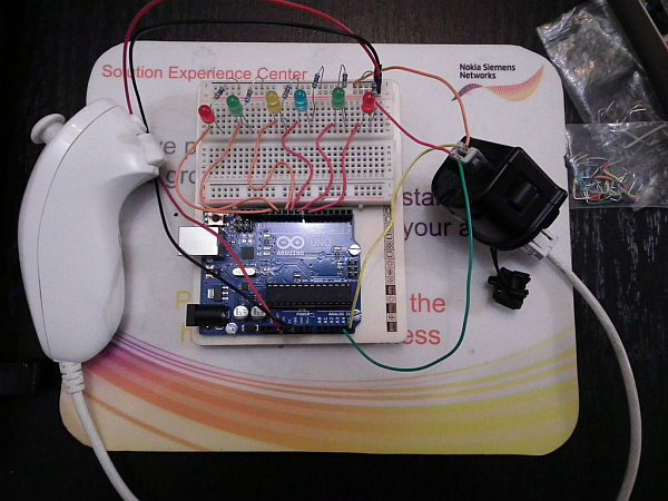
Get 4 cables, and put them in the correct place, in the photo the orange wire is ground, is very important to notice
that the powerline uses 3.3V, dont use the 5V powerline it will not fry your control, but is better to play Safe.
Connect Pin 5 Green cable to Analog 4(A4) and Pin 2 Yellow cable to Analog 5(A5) to the arduino, Pin 1 Red cable to Power 3.3V
and Pin 6 (in the photo the cable is orange) to ground.
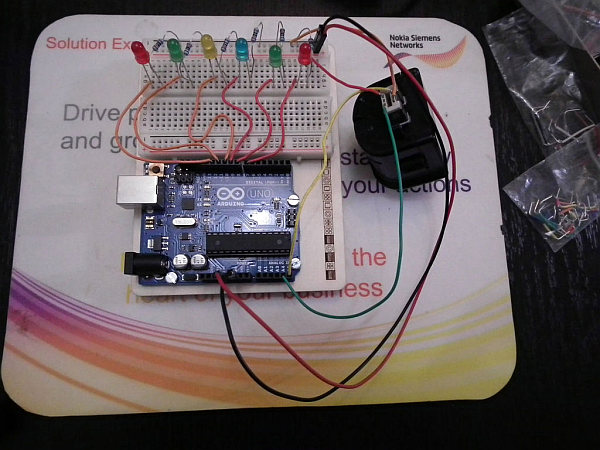
Step 3: Build the led array
The led array is easier to make, remember the anode witch must be connected to the power(digital pin) is the longer leg, and the shorter one must be connected with a 220 ohm resistor to the ground, the pins that you must use are from 7 to 12.
Step 4: The Code
NOTE: I got the original code from this webpage:http://arduino.cc/forum/index.php/topic,8507.0.html
I did not make the code I just fixed it to be able to run in the new Arduino IDE 1.0.2. and I added new code for the
leds, all the credits are for knuckles904.Ok first you need to go to your arduino library and find the Wire carpet then go to Utility and find the archive twi.h open it
with wordpad and delete the lines from //#define ATMEGA8 to #endinf and paste these lines instead:
#define ATMEGA8
#ifndef CPU_FREQ^M
#define CPU_FREQ 16000000L
#endif
#ifndef TWI_FREQ^M
#define TWI_FREQ 100000L
#endif
Save the twi.h archive and now open your arduino IDE and copy and paste the code:
#include <Wire.h>
byte data[6]; //six data bytes
int yaw, pitch, roll; //three axes
int yaw0, pitch0, roll0; //calibration zeroes
void wmpOn(){
Wire.beginTransmission(0x53); //WM+ starts out deactivated at address 0x53
Wire.write(0xfe); //send 0x04 to address 0xFE to activate WM+
Wire.write(0x04);
Wire.endTransmission(); //WM+ jumps to address 0x52 and is now active
}
void wmpSendZero(){
Wire.beginTransmission(0x52); //now at address 0x52
Wire.write(0x00); //send zero to signal we want info
Wire.endTransmission();
}
void calibrateZeroes(){
for (int i=0;i<10;i++){
wmpSendZero();
Wire.requestFrom(0x52,6);
for (int i=0;i<6;i++){
data[i]=Wire.read();
}
yaw0+=(((data[3]>>2)<<8)+data[0])/10; //average 10 readings
pitch0+=(((data[4]>>2)<<8)+data[1])/10;
roll0+=(((data[5]>>2)<<8)+data[2])/10;
}
Serial.print(“Yaw0:”);
Serial.print(yaw0);
Serial.print(” Pitch0:”);
Serial.print(pitch0);
Serial.print(” Roll0:”);
Serial.println(roll0);
}
void receiveData(){
wmpSendZero(); //send zero before each request (same as nunchuck)
Wire.requestFrom(0x52,6); //request the six bytes from the WM+
for (int i=0;i<6;i++){
data[i]=Wire.read();
}
yaw=((data[3]>>2)<<8)+data[0]-yaw0;
pitch=((data[4]>>2)<<8)+data[1]-pitch0;
roll=((data[5]>>2)<<8)+data[2]-roll0;
}
//see http://wiibrew.org/wiki/Wiimote/Extension_Controllers#Wii_Motion_Plus
//for info on what each byte represents
void setup(){
Serial.begin(115200);
Serial.println(“WM+ tester”);
Wire.begin();
wmpOn(); //turn WM+ on
calibrateZeroes(); //calibrate zeroes
delay(1000);
pinMode(11, OUTPUT);
pinMode(12, OUTPUT);
pinMode(10, OUTPUT);
pinMode(9, OUTPUT);
pinMode(8, OUTPUT);
pinMode(7, OUTPUT);
}
void loop(){
receiveData(); //receive data and calculate yaw pitch and roll
Serial.print(“yaw:”);//see diagram on randomhacksofboredom.blogspot.com
Serial.print(yaw); //for info on which axis is which
Serial.print(” pitch:”);
Serial.print(pitch);
Serial.print(” roll:”);
Serial.println(roll);
delay(100);
if (pitch >= 1000){
digitalWrite(12,HIGH);
}
else if (pitch <= -1000){
digitalWrite(11,HIGH);
}
else if (yaw >= 1000){
digitalWrite(10,HIGH);
}
else if (yaw <= -1000){
digitalWrite(9,HIGH);
}
else if (roll >= 1000){
digitalWrite(8,HIGH);
}
else if (roll <= -1000){
digitalWrite(7,HIGH);
}
else {
digitalWrite(11,LOW);
digitalWrite(12,LOW);
digitalWrite(10,LOW);
digitalWrite(9,LOW);
digitalWrite(8,LOW);
digitalWrite(7,LOW);
}
}
1 Breadboard
1 Wii motion Plus
1 Wii Nunchuck
6 Resistors 220 ohm
6 Leds (any color)
Solid core jumper wires
For more detail: Arduino Wii nunchuck and Wii motion plus with updated code for IDE 1.0.2 and LEDs
- How can I connect the Wii controller without an adapter?
You can use the Wii Motion Plus accessory which has a male interface with holes to put wires directly. - Does the power line use 5V or 3.3V?
The power line uses 3.3V; using 5V is not recommended as it might damage the control. - What is the best way to update the code for new Arduino IDE versions?
You must modify the Wire library file twi.h by deleting specific lines and pasting updated definitions for CPU_FREQ and TWI_FREQ. - Can I use the original code found online without changes?
No, the original code is outdated and requires command changes like replacing Wire.send with Wire.write. - Which digital pins should be used for the LED array?
The pins that must be used are from 7 to 12. - How do I identify the correct pinout for the Wiimote side of the Motion Plus?
Pin 1 is Green (SDA), Pin 2 is Orange (Ground), Pin 5 is Red (3.3V), and Pin 6 is Yellow (SCL). - What happens if the pitch value is greater than or equal to 1000?
Digital pin 12 will turn HIGH to light up the corresponding LED. - Where did the original code come from before the modifications?
The original code was obtained from the Arduino.cc forum topic 8507.0 authored by knuckles904.