Summary of Arduino Watch
This Instructables guide details the assembly of a custom Arduino Watch using a Sparkfun Pro Micro, ST7789 1.3" IPS LCD, and a DS3231M RTC chip. The project involves mounting components on PET plate, connecting power and data lines via copper foil tape, removing the power LED to save battery, and wiring specific GPIO pins for display control.
Parts used in the Arduino Watch:
- Sparkfun Pro Micro 3.3 V 8 MHz dev board
- ST7789 1.3" IPS LCD
- 301420 Lipo battery
- 15 mm x 15 mm Lipo charge board
- DS3231M RTC Chip
- MS412FE RTC Battery (optional)
- 20 mm width fabric canvas watch strap
- 1N5822 diode
- Four 6 mm M2 screws
- Copper foil tape
- Wires
- PET plate
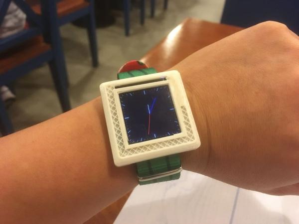
This Instructables show how to make a Arduino Watch from Arduino Watch Core.
Step 1: Preparation
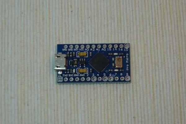
Arduino Dev Board
This time I am using Sparkfun Pro Micro 3.3 V 8 MHz dev board.
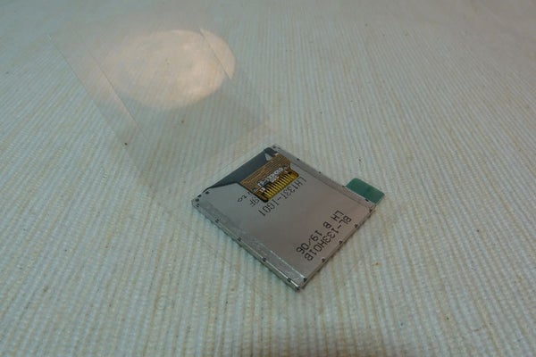
Watch Display
This time I am using a ST7789 1.3″ IPS LCD.
Lipo Battery
I have some 301420 Lipo battery in hand.
Lipo Charge Board
I have some 15 mm x 15 mm Lipo charge board in hand.
RTC Chip
This time I am using DS3231M, it built-in crystal oscillator, no extra component required
RTC Battery
This is optional, in case you want to keep the time even Lipo battery used up. MS412FE is a tiny 1 mAh rechargeable battery, according to the RTC datasheet 1 mAh already can keep time many days.
Watch Strap
I have ordered some 20 mm width fabric canvas watch strap.
Others
A diode e.g. 1N5822, four 6 mm M2 screws, copper foil tape and some wires
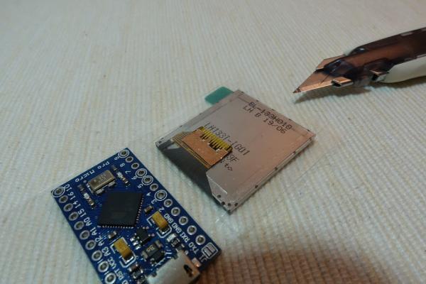
Step 2: Fixing Dev Board & LCD
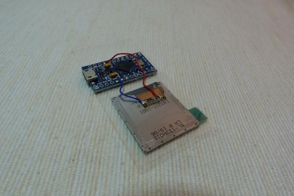
Use a small piece of PET plate to stick the Pro Micro and IPS LCD together.
Step 3: Connect GND
Read the LCD datasheet provided by your vendor.
Cut a little copper foil tape just touch all GND pins and LED negative pins and fix it on the FPC plate. Then soldering the pins with copper foil tape.
Step 4: Connect Power Pins
Connect dev board GND Pins to the copper foil tape. Connect Vcc pins to LCD Vcc pin.
Step 5: Connect LCD Pins
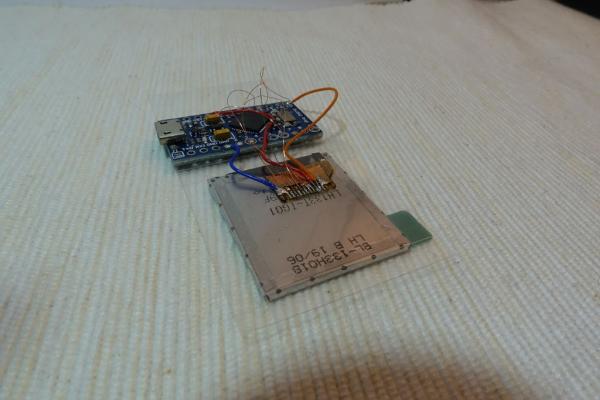
Here are the connection summary:
LCD  -> Arduino
LED+ -> GPIO 10
SDA  -> GPIO 16(MOSI)
SCL  -> GPIO 15(SCLK)
RST  -> GPIO 18(A0)
DC   -> GPIO 19(A1)
CS   -> GPIO 20(A2)
Step 6: Remove Power Led
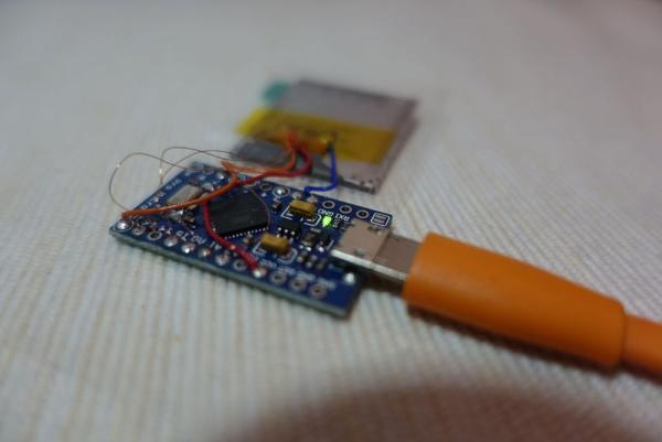
The power LED always on and consume over 1 mA continuously, so it is better remove it. Unsoldering and remove the LED carefully.
Read more: Arduino Watch
- Which microcontroller board is used?
The Sparkfun Pro Micro 3.3 V 8 MHz dev board is used. - What type of display is installed?
A ST7789 1.3" IPS LCD is used. - How should the GND pins be connected?
Cut a little copper foil tape to touch all GND pins and LED negative pins, then solder the pins with the tape. - Why is it recommended to remove the power LED?
The power LED consumes over 1 mA continuously, so removing it saves battery life. - Can the RTC keep time without the main battery?
Yes, an optional MS412FE RTC battery can keep time for many days if the Lipo battery is used up. - Which GPIO pin connects to the LCD RST pin?
The LCD RST pin connects to GPIO 18 (A0). - What material is used to stick the Dev Board and LCD together?
A small piece of PET plate is used to stick them together. - What specific diode is suggested for this project?
A 1N5822 diode is suggested.