
Summary of Arduino Voltmeter Code
This article demonstrates how to build a voltmeter using an Arduino and the voltage divider concept. The project reads analog input, calculates the voltage, and displays the result on a 16x2 LCD screen. The code includes logic to handle signal noise by filtering out readings below a specific threshold.
Parts used in the Arduino Voltmeter:
- 1x 16×2 parallel LCD display (compatible with Hitachi HD44780 driver)
- 1x Arduino
- 1x 10kΩ potentiometer
- 5x 10kΩ resistor
- 2x 2.2kΩ resistor
- Jumper wire
This arduino projects show how to make voltmeter with your arduino. It use voltage divider concept to estimate the voltage input.
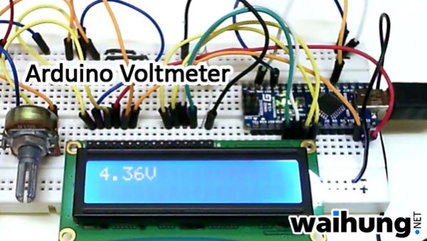
Instruction;
1) Connect all jumper wire as shown in diagram.
Upload this code to your arduino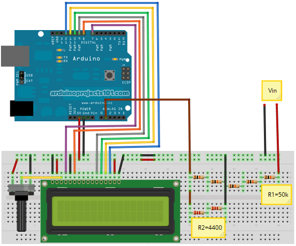
/*
  Voltmeter
  Voltmeter base on voltage divider concept.

  Code based on: http://www.clarenceho.net:8123/blog/articles/2009/05/17/arduino-test-voltmeter
  Coded by: arduinoprojects101.com
*/

// include the library code:
#include <LiquidCrystal.h>

// initialize the library with the numbers of the interface pins
LiquidCrystal lcd(7, 8, 9, 10, 11, 12);

// variables for input pin and control LED
  int analogInput = 1;
  float vout = 0.0;
  float vin = 0.0;
  float R1 = 50000.0;    // !! resistance of R1 !!
  float R2 = 4400.0;     // !! resistance of R2 !!

// variable to store the value
  int value = 0;

void setup(){
  // declaration of pin modes
  pinMode(analogInput, INPUT);

  // set up the LCD's number of columns and rows:
  lcd.begin(16, 2);
  lcd.print("Vin=");
}

void loop(){
  // read the value on analog input
  value = analogRead(analogInput);

  vout = (value * 5.0) / 1024.0;
  vin = vout / (R2/(R1+R2));

  // print result to lcd display
  lcd.setCursor(4, 0);
  lcd.print(vin);
  lcd.print("V");

  // sleep...
  delay(500);
}
Discussion;
a) You might saw some reading 0.06V even there is no Vin supply, this may caused by signal noise. You can add if statement to flush this reading. ie
if (vin<0.09) {
vin=0.0
}
add before print result to lcd display line.
Major Components in Project
Parts List;
1) 1x 16×2 parallel LCD display (compatible with Hitachi HD44780 driver)
2) 1x Arduino
3) 1x 10kΩ potentiometer
4) 5x 10kΩ resistor
5) 2x 2.2kΩ resistor
6) Jumper wire
1) 1x 16×2 parallel LCD display (compatible with Hitachi HD44780 driver)
2) 1x Arduino
3) 1x 10kΩ potentiometer
4) 5x 10kΩ resistor
5) 2x 2.2kΩ resistor
6) Jumper wire
For more detail: Arduino Voltmeter Code
-
What concept does this voltmeter use to estimate input voltage?
The project uses the voltage divider concept to estimate the voltage input. -
How can I fix reading errors showing 0.06V when there is no supply?
You can add an if statement to flush the reading caused by signal noise, such as setting vin to 0.0 if it is less than 0.09. -
Which library is required for the LCD display in the code?
The LiquidCrystal library must be included to initialize the interface pins. -
What are the resistance values defined for R1 and R2 in the code?
R1 is set to 50000.0 ohms and R2 is set to 4400.0 ohms. -
How often does the code update the display?
The loop includes a delay of 500 milliseconds between updates. -
Can this project work with any LCD display?
No, it requires a 16×2 parallel LCD display compatible with the Hitachi HD44780 driver. -
Where should the noise filtering code be placed?
The if statement to filter noise should be added before printing the result to the LCD display line.
