
Summary of Arduino Vacuum Gauge Display
This project involves an Arduino-based vacuum gauge display system. The setup includes a vacuum gauge with a 0-10VDC output, modified to 0-5VDC using a potential divider for Arduino compatibility. An OLED screen is mounted directly on the Arduino board, powered by a 12V-to-5V PSU that also supplies the vacuum gauge via an RJ45 input port. A custom-designed and 3D-printed case houses the components, featuring a button that activates a diagnostics mode when held.
Parts used in the Arduino Vacuum Gauge Display:
- Vacuum gauge (0-10VDC output)
- Potential divider (to convert 0-10VDC to 0-5VDC)
- Arduino microcontroller
- OLED screen
- 12V-to-5V power supply unit (PSU)
- RJ45 input port (for 12V DC input)
- Custom 3D-printed case (designed in Autodesk Inventor)
- Custom 3D-printed button
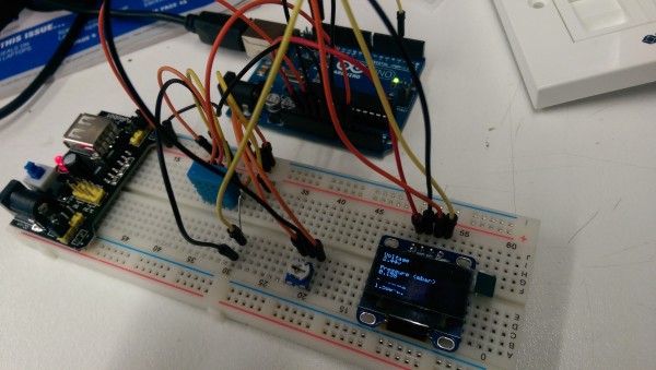
Initial testing. Ignore the humidity sensor, that was for something else. The vacuum gauge outputs 0-10VDC. This had to be changed to a 0-5VDC range using a potential divider so it was compatible with the Arduino. Initial build used a 10k pot in place of a vacuum gauge to make it simpler.
The OLED screen simply plugs in over the arduino which made for a nice compact board.
A custom pcb would’ve looked nicer but this worked.
12v – 5v PSU used to power the arduino.
12v DC comes in through the top RJ45 port and is passed straight through to the vacuum gauge as well as to the 12v-5v PSU.I designed the case in Autodesk Inventor and had it printed.Had this little button printed too which sits in…
…a guide on the underside. I had the button made slightly longer than needed, then sanded it so it fits exactly between the top of the button and the case when fully assembled. Was very pleased with how that turned out.
Holding the button in is a kind of ‘diagnostics’ mode which shows more information.
Under normal operation it simply shows the vacuum pressure.
For More Details: Arduino Vacuum Gauge Display
-
How was the vacuum gauge signal adapted for the Arduino?
The 0-10VDC output from the vacuum gauge was changed to a 0-5VDC range using a potential divider. -
What component was initially used instead of the vacuum gauge during testing?
A 10k pot was used in place of the vacuum gauge to simplify the initial build. -
How is the OLED screen connected to the Arduino?
The OLED screen plugs directly over the Arduino, creating a compact board setup. -
What powers the Arduino and the vacuum gauge in this project?
A 12V-to-5V PSU powers the Arduino, while 12V DC from the RJ45 port powers both the PSU and the vacuum gauge. -
How was the case for the project created?
The case was designed in Autodesk Inventor and then 3D printed. -
How does the button function in normal operation versus diagnostics mode?
In normal operation, it shows vacuum pressure; holding the button activates a diagnostics mode showing more information.
