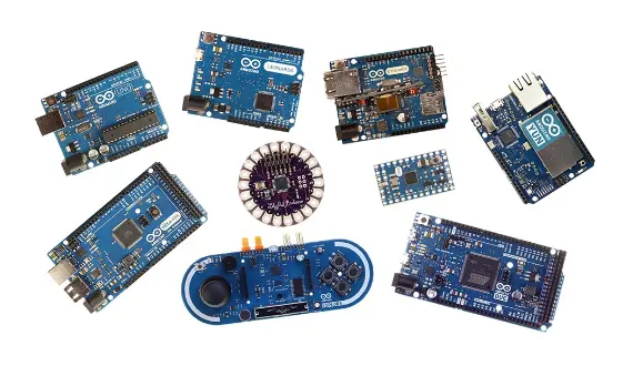
The popularity of Arduino boards has skyrocketed in recent times, thanks to the growing demand for automation in the market. These microcontrollers have become the go-to option for beginners looking to embark on their project-building journey, offering unparalleled ease of use and a wide range of options. Arduino has released several common boards that make it easier for users to get their job done efficiently.
In this article, we will explore the three most commonly used Arduino boards: Arduino Uno, Arduino Mega, and Arduino Micro. We will delve into their technical specifications, major differences, and provide tips to help you choose the right Arduino board for your project.
What is an Arduino Microcontroller?
Arduino is an open-source hardware development board that allows users to develop projects and interact with the real world. It is a powerful tool for solving real-world problems and provides access to the world of microcontrollers. The controller used in Arduino is based on the ATmega AVR microcontroller, and it utilizes a development part called Arduino IDE. By using the C++ programming language, Arduino automates tasks and offers a wide range of learning opportunities. However, it is important to consider the drawbacks of Arduino when selecting the best board for your project.

Arduino Microcontroller: Pros and Cons
Let’s start with the advantages of using an Arduino board:
- Easy to use: Arduino is known for its simplicity and user-friendly interface. It employs simple programming languages like C and C++, making it ideal for beginners. The board itself has a minimal hardware interface, making it easy for users of all levels of expertise.
- Cross-platform support: Unlike some microcontrollers that are limited to Windows, Arduino provides support for Windows, Linux, and macOS, making it accessible to a wider range of users.
- Cost-effective: Arduino boards are surprisingly affordable, making them accessible to regular users. Additionally, the IDE required to operate the board is an open-source platform, further reducing project costs.
- Libraries: Arduino offers a wide range of libraries that enhance its functionality. These libraries enable users to control external modules, motors, and sensors, making integration with external devices a breeze.
- Active user community: Arduino’s open-source nature has fostered a vibrant online community. Users can find support and inspiration from various projects and discussions on Arduino forums.
On the other hand, there are a few limitations to keep in mind:
- Lack of multitasking: Unlike Raspberry Pi, Arduino can only run a single program at a time. Users must shut down one program to execute another on the Arduino board.
- Limited memory: Arduino boards have limited storage capacity. For example, the popular Arduino Uno board has 2KB of SRAM and 32KB of flash memory. This means that only a few hundred lines of code can be used, making Arduino more suitable for educational purposes rather than large-scale industrial projects.
- Communication limitations: Arduino boards are limited to Wi-Fi and Bluetooth platforms. To enable these features, additional hardware is required, which can increase the overall project cost.
- Limited programming language support: Arduino boards primarily support C and C++, lacking support for languages like Python, Java, and JS. This limits their application to specific areas.
- Lack of optimization: The microcontrollers used in Arduino boards are optimized for beginners, prioritizing ease of use over performance. If the same microcontrollers were used with AVR, performance could be improved.
Arduino Uno: The Open-Source Microcontroller Board
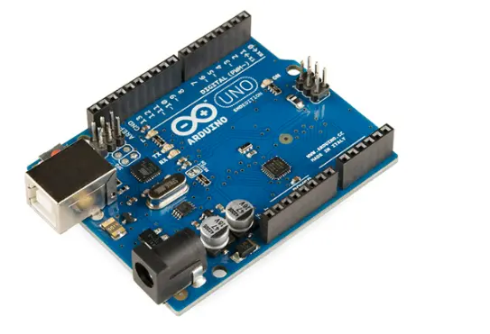
Arduino Uno is a widely used open-source microcontroller board based on the Microchip ATmega328P microcontroller. It is an excellent choice for beginners looking to explore electronic and coding applications in their projects. Arduino Uno was the first board released by Arduino.cc and is known for its user-friendly nature. The board features a combination of digital and analog pins, including 6 analog pins and 14 digital pins, along with a USB port for serial communication, a power jack, and ICSP headers. Six of the 14 digital pins can be used as PWM outputs. Additionally, it is equipped with a 16MHz crystal oscillator that provides the clock signal and synchronizes communication on the board.
The board can be powered by a USB cable or an external 9V battery supply. Arduino Uno is programmed using an integrated development environment (IDE) that can be accessed both online and offline. The ATmega328 microcontroller allows for the uploading of new code without the need for external hardware, thanks to its pre-programmed bootloader.
Arduino Uno is one of the most popular Arduino boards and is available in two versions: surface mount (SMD) and through-hole, which utilize either surface mount or through-hole ATmega328 components.

The Arduino Uno board can be powered either through a USB cable or an external power supply. For external power, you can use either a battery or an AC-DC adapter. When plugging in the adapter, make sure to use a 2.1mm center-positive plug. To connect a battery, insert leads into the GND and VIN pin headers on the POWER connector. The board can operate within a voltage range of 6 to 20 volts, depending on the external power supply. However, supplying less than 7V may cause instability, while using more than 12V can lead to overheating and damage. The optimal voltage range for the Arduino Uno board is between 7-12V.
The power pins on the Arduino Uno board are configured as follows:
VIN: This pin is used to provide input voltage to the Arduino board when using external power.
5V: These pins output a constant 5V supply through a regulator on the board. You can supply power to these pins from the VIN pin, a DC power adapter, or the USB connector. However, ensure that the proper voltage is supplied through this pin.
3.3V: The onboard regulator generates a 3.3V supply, with a maximum current of 50mA.
GND: This pin provides the ground connection for the Arduino board.
Communication Process
The Arduino Uno board can communicate with computer devices and other microcontrollers. It supports the UART TTL (5V) serial communication protocol through digital pins 0 (RX) and 1 (TX), which serve as receiver and transmitter pins, respectively. The ATmega16U2 chip on the board acts as a virtual COM port, enabling serial communication over USB. The necessary USB COM drivers are included in the 16U2 firmware, eliminating the need for external driver installation. The Arduino software’s serial library facilitates serial communication through the digital pins on the board. Additionally, the Arduino Uno board supports SPI and I2C communication, which can be utilized with the SPI and Wire libraries, respectively.
Memory
The ATmega328 microcontroller on the Arduino Uno board has a total storage capacity of 32KB, with 0.5KB allocated for the bootloader. It also has 1KB of EEPROM and 2KB of SRAM. The pinMode(), digitalWrite(), and digitalRead() functions allow for input and output on any of the 14 digital pins on the Uno. Each of these pins operates at 5V with a maximum current of 40mA and has an internal pull-up resistor with a value between 20-50k Ohms.
Some of the pin configurations on the Arduino Uno board include:
Serial Pins: Pins 0 (RX) and 1 (TX) are used to receive and transmit TTL serial data.
External Interrupts: Pins 2 and 3 can trigger an interrupt on a low value, change in value, or rising and falling edges.
TWI (Two-Wire Interface): A4 (SDA) and A5 (SCL) pins support TWI communication and can be used with the Wire library.
AREF: This pin is the reference voltage for the analog pins and can be used with the analogReference() function.
Reset: This pin is used to reset the microcontroller when necessary.
LED-Pin 13: This pin controls the built-in LED on the board, turning it on when the pin is high and off when the pin is low.
Arduino Mega
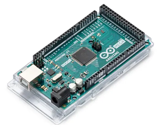
The Arduino Mega is a microcontroller board based on the ATmega2560. It is the largest board in the Arduino series, featuring 54 digital input and output pins, with 14 of them capable of PWM output. It also has 16 analog inputs and 4 UART ports for serial communication. The board includes a 16MHz crystal oscillator, USB connector, reset buttons, ICSP header, and power jack, providing all the necessary components for the microcontroller to operate. The Arduino Mega is fully compatible with all Arduino designs.

Power:
The power pins on the Arduino Mega board are as follows:
– VIN: This is the input voltage for the Arduino board.
– 5V: This pin provides a regulated and constant power supply to the microcontroller and other components on the board.
– 3.3V: This pin generates a 3.3V supply through the onboard regulator, with a maximum current draw of 50mA.
– GND: This is the ground pin for the microcontroller.
Input and Output Pins:
Each of the 54 pins on the Arduino Mega can be used as both input and output pins, utilizing functions such as pinMode(), digitalWrite(), and digitalRead().
Serial Pins:
The Arduino Mega has pins 0 (RX) and 1 (TX) specifically for receiving and transmitting TTL serial data. These pins are connected to the corresponding pins of the Arduino Mega USB to TTL serial chip.
External Interrupt:
Certain pins on the Arduino Mega can initiate interrupts based on low, rising, or falling edges, or when the value changes.
PWM Pins 0-13:
These pins provide 8-bit PWM output signals and can be used with the analog write function.
I2C Pins 20 (SDA) and 21 (SCL):
The Arduino Mega supports the I2C wire library and has these dedicated pins for I2C communication.
Analog Inputs:
The Arduino Mega has 16 analog input pins, providing 10 bits of resolution. The AREF pin and analogReference() function allow you to change the upper end of the analog input range from the default range of ground to 5 volts.
AREF:
This pin serves as the reference voltage for the analog inputs and is used with the analog references() function.
RESET:
The RESET pin is used to reset the microcontroller.
Communication:
The Arduino Mega 2560 offers multiple communication options for connecting with computer devices. It has 4 hardware UART for TTL 5V serial communication, and the ATmega chip provides a virtual com port to the computer software. The board also supports serial communication through a library, as well as I2C and SPI communications.
Arduino Micro
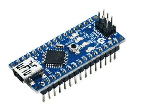
The Arduino Micro is a microcontroller board based on the Atmega32U4. It features 20 digital input/output pins, 12 analog pins, and 7 PWM outputs among the 20 digital pins. The board includes a micro USB connection port, reset button, and ICSP header. The 16 MHz crystal oscillator on the Arduino Micro helps synchronize the clock signal, and the USB port allows communication between the board and the computer. Serial communication is used to interface with computer devices.

Pins Configuration of Arduino Micro:
The digital pins on the Arduino Micro can be configured as either input or output using the digitalWrite(), digitalRead(), and pinMode() functions. The board operates at a voltage of 5V, and each pin can handle a current of up to 40mA. There is also an internal pull-up resistor with a value between 20-50 kiloohms.
Pin Description:
– Serial Pins 0 (RX) and 1 (TX): These pins are used for receiving and transmitting TTL serial data using the ATmega32U4 microcontroller.
– TWI Pins 2 and 3: These pins are used for TWI communication and are supported by the wire library.
– External Interrupts: Certain pins on the board can be configured to activate an interrupt based on value changes, rising or falling edges, or other conditions.
– PWM: The analogWrite() function can be used to generate 8-bit PWM output signals.
– Analog Inputs (A0-A11): The Arduino Micro has 12 analog input pins that can also be used as digital input/output pins. Each pin has 1024 unique values.
– SPI: The SPI library is used for SPI communication, and these pins are not connected to any of the digital pins.
– LED 13: This is an onboard LED similar to those found on Arduino Uno and Mega boards. It is set to high when the corresponding pin receives a high signal.
– AREF: This pin is used as the reference voltage for analog inputs and works with the analogReference() function.
– RESET: The reset pin is used to reset the program running on the microcontroller when needed.
Power Connection Pins:
– VIN: This pin is used to provide input voltage to the Arduino Micro when an external power supply is used. It can also receive a 5V input voltage through the USB connection port.
– 5V: This regulated power pin provides a constant 5V supply. It can be powered either through VIN or the regulated 5V power source.
– 3V: This pin generates a 3.3V supply through the board’s regulator and can provide a maximum current of 50mA.
– GND: This is the ground pin used for grounding the board.
Differences between Arduino Uno and Arduino Micro:
Dimensions:
– Arduino Uno: 2.7″ x 2.1″
– Arduino Micro: 1.88″ x 0.7″
Connectivity:
– Arduino Uno: 12 I/O pins, 6 PWM pins, 6 analog pins
– Arduino Micro: 20 I/O pins, 7 PWM pins, 12 analog pins
Computing:
– Arduino Uno: ATmega328P processor, 32kb flash memory, 2kb SRAM
– Arduino Micro: ATmega32U4 processor, 32kb flash memory, 1kb EEPROM, 2.5kb SRAM
Communication:
– Both Arduino Uno and Arduino Micro support serial communication, SPI, and I2C.
Differences between Arduino Uno and Arduino Mega:
Dimensions:
– Arduino Uno: 2.7″ x 2.1″
– Arduino Mega: 4″ x 2.1″
Connectivity:
– Arduino Uno: 14 I/O pins, 6 PWM pins, 6 analog pins
– Arduino Mega: 54 I/O pins, 15 PWM pins, 16 analog pins
Computing:
– Arduino Uno: ATmega328P processor, 32kb flash memory, 2kb SRAM
– Arduino Mega: ATmega2560 processor, 256kb flash memory, 8kb SRAM, 4kb EEPROM
Communication:
– Both Arduino Uno and Arduino Mega support serial communication, SPI, and I2C.
Setting up Arduino Boards:
All Arduino microcontrollers can be programmed using the Arduino software. They come with a pre-burned bootloader, allowing you to upload new code without the need for external hardware. The ATmega firmware source code is available in the Arduino repository.
Communication with the Arduino boards is done through a USB connection, which acts as a virtual com port for the software. The Arduino IDE software includes a serial monitor that facilitates sending and receiving data in text format. The software serial library enables communication on the digital pins of the Arduino boards.
Tips for Selecting the Right Arduino Boards:
When selecting the appropriate Arduino board for your project, there are several factors to consider. One important factor is the pin configuration. If you require more I/O pins or analog pins for your output devices, the Arduino Mega is the best choice as it offers more I/O pins compared to Arduino Uno and Arduino Nano.
If you are concerned about the size of your circuit and have a small number of external devices, the Arduino Nano is a suitable option. It reduces the overall cost of the project.
Conclusions:
Arduino is a microcontroller designed for rapid prototyping, particularly for beginners. Creating your PCB prototype for Arduino, you have simple access to the board’s schematic and those of any Arduino shields.
