Summary of Arduino Throttle Body Syncronization Shield
This article details the construction of a custom Arduino-based Throttle Body Synchronization (TBS) shield to smooth motorcycle engine idles. The author replaces traditional fluid-based tools with an electronic solution, designing a PCB using Eagle software and assembling four vacuum sensors to measure cylinder-specific vacuum levels. The project involves researching sensor specifications, creating a schematic, ordering custom PCBs, and manually soldering surface-mount components to interface with an Arduino for real-time vacuum monitoring.
Parts used in the Arduino Throttle Body Synchronization Shield:
- (4) Custom produced PCBs from SilverCircuits.com
- (4) Vacuum sensors MPXV5050VC6T1CT-ND
- (4) 470.0 pf ceramic capacitors (surface mount 0603)
- (4) 0.01 uf ceramic capacitors (surface mount 0603)
- (4) 1.0 uf ceramic capacitors (surface mount 0603)
- Pin headers (four sets of 2 pins and four sets of 4 pins)
- Standard engine vacuum hose (1/8th inch inner diameter)
- Soldering iron with a flat tip
- Fine high quality solder
- Solder flux liquid
- Vision enhancement tool (reading glasses with magnification)
- Solder helper with alligator clips
- Alcohol and Q-Tips for cleaning
A common Motorcycle maintenance task is to synchronize the throttle bodies on the engine to smooth out any rough idle. This is done by monitoring the vacuum on each throttle body and using the idle screw to make the adjustment.
While this sounds rather advanced, with a little knowledge, a few standard tools to access the engine, and a TBS tool (Throttle Body Synchronization); the maintenance item really isn’t that hard.
Now you can buy a tool or build a TBS tool using fluids and tubes (there are examples of this out there on the interwebs), but I wanted to use an Arduino and some electronics to build my own to do the job. This instructable describes my journey in making my own Arduino Throttle Body Synchronization shield.
Step 1: Research
A TBS tool is rather simple in what it does; it will measure the vacuum that each cylinder is actively producing when the engine is running. To measure vacuum with an Arduino I needed to build a shield that would contain a vacuum sensor for each cylinder on my engine (4 in my case).
There are many vacuum sensors available from your favorite electronics parts stores. The interesting range that I need to measure is around -33 kPa (-4.78 psi). This is the value that should be measured on my motorcycle on a single cylinder when the engine is warm and at idle. You should consult a service manual for the specifics for your engine. So I picked one that measured a range between 0 kPa to -50 kPa.
Then I needed to understand how to connect this to my engine. The service manual helps here also, but I also found many great write ups on the web. I just needed some standard engine vacuum hose with an inner diameter of 1/8th inch which will push onto a service nipple already present on the throttle body. This same hose will directly push onto the vacuum sensor. I found this in bulk at my local automotive store. I needed four hoses each with at least 3 feet length so I could put the Arduino and sensors in a safe place.
Step 2: Designing the Shield
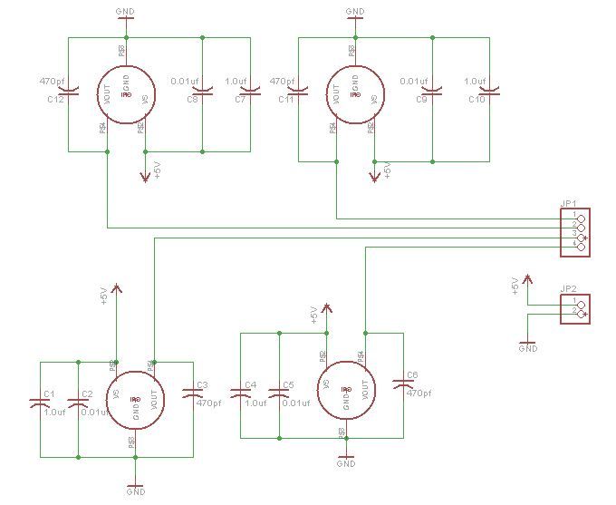
The sensor I picked required a pretty simple schematic. It just needed three capacitors. Further, providing that it got 5v to run on it would provide an analog voltage that represented the vacuum reading in the range of 4.6v ( at 0 kPa) to 0.1v (-50 kPa). This is great for connecting directly to the Arduino analog input pins.
I used the free version of Eagle to design the first sensor schematic. Eagle is a PCB design software that is commonly used by many hobbyist to design schematics and layouts for circuit boards. There are many videos and instructions on how to use Eagle, and like all moderately complex software it just takes a little time using it to become familiar with how it works.
Then all I had to do was replicate the schematic for a single sensor four times and add the connector for pushing the shield onto the Arduino.
With the schematic complete, I switched to board layout mode and followed some other shield layouts to build an outline that would simply press onto an Arduino like all shields do. I finished it by then placing all the parts and running all the trace lines.
Once I had the completed design and layout, I did research and found a company that did PCB prototype creation. They accepted Eagle files directly, making it easy to upload, pick the number I wanted, and submit my order. I then just needed to wait for my boards to be shipped to me.
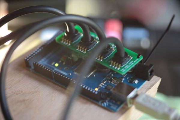
Step 3: Assembling the shield
I collected all the parts, brought out the boards, and setup my tools.
(4) vacuum sensors MPXV5050VC6T1CT-ND
(4) 470.0 pf ceramic capacitors (surface mount 0603) 478-6201-1-ND
(4) 0.01 uf ceramic capacitors(surface mount 0603) 445-5100-1-ND
(4) 1.0 uf cermic capacitors(surface mount 0603) 311-1445-1-ND
I had pin headers from a previous project that split into eight sets, four sets of 2 pins and four sets of 4 pins.
I suggest a good quality soldering iron when soldering surface mount parts by hand. There are many techniques to soldering surface mount parts, some are better when you have a lot of soldering to do; but I just do it by hand. Again, searching the interwebs will give you lots of ideas. While a fine tip on the soldering iron is not a requirement, I found that a flat tip that wasn’t too large was very helpful. Also use fine high quality solder.
Having a solder helper is also very handy. Mine has multiple alligator clips to pinch the board in and they can rotate to hold the board flat. Further, mine also has a tray in the base to hold the solder spool.
I found having some sort of vision enhancement was a requirement. While my vision is still very good, I could not imagine soldering such small parts without some magnification. I found using reading glasses with a decent magnification works really well. I only lost two capacitors out of the 12 I had to solder in. They were close to the size of a grain of sand. Next time I will use larger SM parts.
I applied a little solder flux liquid (comes in a bottle) to each SM pad and a little between. This stuff is sticky and helps hold the part to the board while you solder. Then I lightly press the soldering iron to one side while being careful not to move the part. I then hold some solder to what little of the pad that is left showing next to the part lead, and it will just flow around the pad and lead. Let it cool for 15 seconds and then repeat for the other leads.
Once complete, I used some alcohol and a Q-Tip to wash away any left over solder flux to clean up the board.
(4) vacuum sensors MPXV5050VC6T1CT-ND
(4) 470.0 pf ceramic capacitors (surface mount 0603) 478-6201-1-ND
(4) 0.01 uf ceramic capacitors(surface mount 0603) 445-5100-1-ND
(4) 1.0 uf cermic capacitors(surface mount 0603) 311-1445-1-ND
For more detail: Arduino Throttle Body Syncronization Shield
- What is the primary purpose of this project?
The project builds a custom Arduino shield to synchronize throttle bodies on a motorcycle engine to smooth out rough idles by measuring vacuum. - How many vacuum sensors are required for this specific build?
Four vacuum sensors are needed because the author's engine has four cylinders. - What voltage range does the selected sensor output represent?
The sensor provides an analog voltage ranging from 4.6v at 0 kPa to 0.1v at -50 kPa when powered by 5v. - Can I use standard engine vacuum hose for this project?
Yes, you need standard engine vacuum hose with an inner diameter of 1/8th inch that fits service nipples and vacuum sensors. - Which software was used to design the circuit board?
The free version of Eagle was used to design the first sensor schematic and the final board layout. - What type of tips are recommended for the soldering iron?
A flat tip that is not too large is very helpful, though a fine tip is not strictly required. - Why is vision enhancement necessary during assembly?
Magnification is required because the surface mount parts are extremely small, comparable to the size of a grain of sand. - What tool helps hold the board flat during soldering?
A solder helper with multiple alligator clips is used to pinch the board and rotate it to keep it flat. - How do you clean the board after soldering?
You should use alcohol and a Q-Tip to wash away any leftover solder flux. - What vacuum range should be measured for a warm engine at idle?
The interesting range to measure is around -33 kPa (-4.78 psi), though a sensor covering 0 to -50 kPa was chosen.