
Summary of Arduino The 5$ Karduinoss pad
This article details a low-cost DIY MIDI controller project using an old laptop Synaptics touchpad and an Arduino. The author explains how to solder wires to the touchpad's test points, connect it to an Arduino, and use specific code libraries to translate touch coordinates into MIDI signals via ttymidi. The project offers a budget-friendly alternative to expensive hardware like Kaoss pads, though it lacks built-in audio output.
Parts used in the 5$ Karduinoss Pad:
- Synaptics touchpad from an old laptop
- Arduino (or bare ATMEGA168 chip)
- Pretinned wires
- Hot glue or similar product for strain relief
- LED connected to pin 3
So, looking at these Kaoss pads and alike hardware, I found that there is hardly any point in this device being so expensive, when you just want to use it as MIDI controller.
Going through my parts bin, I found a Synaptics touchpad from an old laptop and figured this should just work as a replacement.
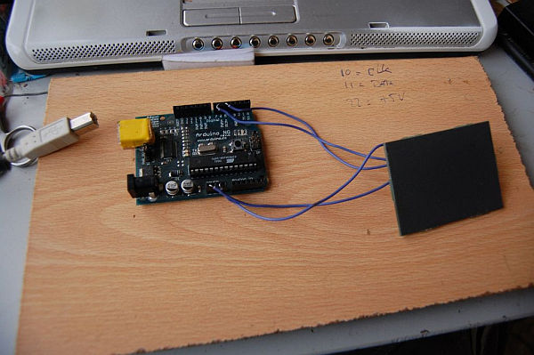
Ok, when I say 5$, i mean really cheap. Clearly a loose arduino is already 20-25 USD (but you can replace it with just a bare ATMEGA168 chip for ~2 USD) , and this touchpad would probably cost you some money aswell, when you are not able to salvage it from an old laptop.
WARNING: the Kaoss pads and similar hardware all have built-in audio outputs, this project does not .
Step 2: Soldering to the touch-pad
Well, this is simple enough, bring out the points you have found 😀
The main trick is to use pretinned wires and first get a small island of solder on the testpoints you have found. Be careful to not put too much heat on the touch-pad, the copper can very easily get loose from the pad by overheating.
For ground I soldered to the big square connection (see also the pin-out image), but there are many more places where you can get ground signal.
After this step, you probably want to secure your soldering with some hot glue or similar product for strain relief.
Step 3: Interfacing to the arduino.
As you now have a touch-pad with wires attached to it, lets look into getting values from it.
The available ps2 libraries for arduino naturally work as a mouse and allow for mouse type input, if you’re into such a thing 😉
Below you will find a karduinoss.pde sketch for the arduino based on the ps2 library available on http://www.arduino.cc/playground/ComponentLib/Ps2mouse which will initialize the touch-pad as an absolute xy controller with about ~4000 steps side to side.
The code does some auto-calibration based on the values it gets, and maps the x, y and z values to MIDI controller changes through the use of ttymidi available on http://www.varal.org/ttymidi/.
The karduinoss.pde sketch assumes an LED is connected to pin 3 ,the touch-pad clock on pin 13 and the touch-pad data on pin 12.
For more detail: Arduino The 5$ Karduinoss pad
- What is the main purpose of this project?
To create a low-cost MIDI controller using a salvaged laptop touchpad. - Can this device replace expensive hardware like Kaoss pads?
It serves as a functional replacement for MIDI control but does not have built-in audio outputs. - How much does the core microcontroller cost if not using a full Arduino?
A bare ATMEGA168 chip costs approximately 2 USD. - Which library initializes the touchpad as an absolute xy controller?
The karduinoss.pde sketch uses the ps2 library available on the Arduino Playground. - How many steps does the touchpad provide side to side?
The setup maps values to about 4000 steps side to side. - What software translates the touch values to MIDI changes?
The project uses ttymidi to map x, y, and z values to MIDI controller changes. - Which pins are used for the touchpad clock and data?
The touchpad clock connects to pin 13 and data connects to pin 12. - Is an LED required for the circuit?
The provided sketch assumes an LED is connected to pin 3.
