Summary of Arduino Modules – Flame Sensor
This guide explains how to set up and test a Flame Sensor module with an Arduino for short-range fire detection. The sensor detects IR wavelengths between 760 nm and 1100 nm, offering both analog and digital outputs. It operates effectively within a range of approximately three feet, though testing requires the flame to be within one foot. Users can adjust sensitivity via a potentiometer on the digital output and connect the device using standard jumper wires to power the Arduino safely.
Parts used in the Flame Sensor Project:
- Flame Sensor (model with an analog out)
- Male to Female jumper wires
- An Arduino (any flavor)
- Lighter or another flame source for testing
Quick and simple start guide for using and exploring the Flame Sensor module with an Arduino.
The model in the example I am using is from Deal Extreme [DX] and can be found HERE.
(The instructable for the Rain Sensor is now available!)
Materials needed:
- Flame Sensor (model with an analog out)
- Male to Female jumper wires
- An Arduino, any flavor.
- Lighter or another flame source for testing.
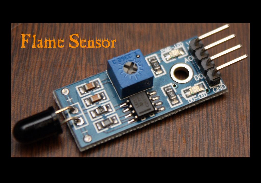
Step 1: Getting to know your Flame Sensor:
Usage:
These types of sensors are used for short range fire detection and can be used to monitor projects or as a safety precaution to cut devices off / on.
Range:
I have found this unit is mostly accurate up to about 3 feet.
How it works:
The flame sensor is very sensitive to IR wavelength at 760 nm ~ 1100 nm light.
Analog output (A0): Real-time output voltage signal on the thermal resistance.
Digital output (D0): When the temperature reaches a certain threshold, the output high and low signal threshold adjustable via potentiometer.
Pins:
VCC…… Positive voltage input: 5v for analog 3.3v for Digital.
A0………. Analog output
D0……… Digital output
GND….. Ground
Dimensions:
1.18 in x 0.59 in x 0.20 in (3.0 cm x 1.5 cm x 0.5 cm)
Weight:
0.28 oz (8 g)
Step 2: Testing and Troubleshooting:
Testing:
To test the Flame Sensor and ensure that it is working correctly connect the VCC to a 5v power source and GND. Move a flame source with in a foot of the front of the Ir sensor and the D0-LED should light up.
Troubleshooting:
If the D0-LED does not light up check the following:
- Is the power source 5v?
- Is the ground hooked up?
- Is the flame with in 1 foot and in Line of Sight?
If none of the previous makes the D0-LED light up, your sensor may be defective.
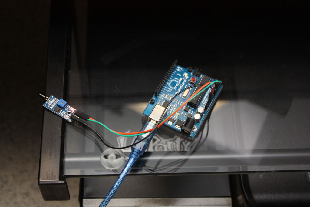
Step 3: Wiring to an Arduino:
To wire the Flame Sensor to the Arduino simply connect the following as shown:
Flame sensor …………… Arduino
VCC…………………………. 5v
GND………………………….GND
A0……………………………. Analog in 0
For more detail: Arduino Modules – Flame Sensor
- What is the primary usage of this flame sensor?
These sensors are used for short range fire detection and can monitor projects or act as safety precautions. - How far can this unit accurately detect a flame?
The unit is mostly accurate up to about 3 feet. - Which light wavelengths does the sensor detect?
The sensor is sensitive to IR wavelength at 760 nm ~ 1100 nm light. - Can I adjust the threshold for the digital output?
Yes, the output high and low signal threshold is adjustable via a potentiometer. - What voltage should I use for the VCC pin?
You should provide 5v for analog input or 3.3v for digital input. - Why might the D0-LED not light up during testing?
It could be due to incorrect power voltage, unconnected ground, or the flame being out of line of sight or too far away. - What is the correct wiring connection for the analog output?
The A0 pin on the sensor connects to Analog in 0 on the Arduino. - Does the sensor work without a flame source nearby?
No, testing requires moving a flame source within a foot of the front of the Ir sensor.