Before i start this AMAZING tutorial on how to build a physical windows volume mixer, i want to apologize for my bad written English. Now, let’s get started.
For this project I would like to build a sound mixer, but with a tft screen so i can see what I’m doing. I know there is a lot of projects like mine, but their can only control 5 apps while I can control thousand.
For this project you will need :
- Arduino Uno/Nano x1
- 1.8′ TFT screen that use SPI x1
- USB A to USB B cable x1
- Push button x3
- Potentiometer x1
- M3 screw (18 to 38 mm long) x4
- Some resistors
Like you see, you don’t need that much items. I bought almost all of them on “Aliexpress” and it cost me around 10 $.
Step 1: Make the Circuit
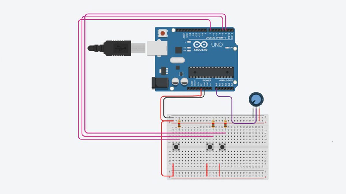
I started to build the circuit on a breadboard and test everything out. For this step, you just have to follow the schematics or follow the following instructions.
- Plug the potentiometer
- Left pin connected to GND
- Right pin connected to 5V
- Center pin connected to A0
- Plug the button
- One pin is connected to 5V
- The second pin as to be connected to a digital input
- There is only 2 interrupt pin on Arduino Uno so I have to connect the third button on DigitalPin7.
- Plug the screen
- GND connected to GND
- VDD connected to 5V
- SCL connected to Digital 13
- SDA connected to Digital 11
- RST connected to Digital 9
- DC connected to Digital 8
- CS connected to Digital 10
- BLK connected to 3.3V
/!\ You have to add pull up/down resistor on all buttons to use it correctly /!\
To do it just plug a high value resistor connected to the DigitalPin and to ground at the same time and its done.
Step 2: The Code : the Worst Part of All Time
Well obviously some people would love to code but, I don’t.
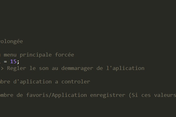
All the code has been written by hand on Arduino IDE. As I’m French all the variable names are written in French but don’t panic, with the help of google translate you could understand it easily.
Itis a little messy but I will show you what to change if you want to custom it.
- First thing you can change is the time before sleep mode. There is a variable on line 14 which is called “TEMPS_VEILLE” . By default the time is 20 seconds.
- Second thing is time before everything goes back to the main menu. You can change it by changing on line 16 the variable called “TEMPS_RETOUR_MENU_PRINCIPAL”
- Last but not least on line 18 you can change the sound volume when the device will be plug. By default its at 50%. The variable name is “INITIAL_SON”
Now the data come out from your Arduino but you have to receive it on your computer. To do this job I used deej.
Deej is a nicely premade program that run on windows/Linux. For those who own an apple devices, I’m sorry but it will not work.
To use it just download it and launch it by using admin right. Then you will need to change the config.yaml by the one I will give you.
On games menu, if your games doesn’t work just add it under all the games names after the number 14 :
Step 3: 3D Modeling
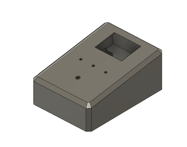
Well this was my first experiences with 3d modeling but I thing the result is quite good. I used fusion 360 because the software was totally free for students.
In this part you have a lot of thing to do, unless you need to make your own design.
If you want to do it by yourself, don’t forgot to add some air outlet to fresh up all the components.
Step 4: 3D Printing
For this part you will need a 3D printer or to buy all the part online.
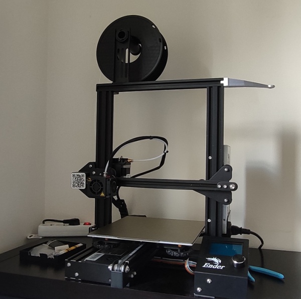
I personally own a ender 3 a little customized.
I sliced all the files with “cura slicer” … I tried to use “ideamaker” but for the moment I’m not used to it yet .
Now lets print !
it took me 15 hours to print the upper part and 6 hours to print the lower part .
I printed it at 210° degree and the bed was at 60° . Due to my bad bed leveling skills I had a little bit of warping and some problem with support . If you want to avoid this problem just level your bed carefully and use tree support.
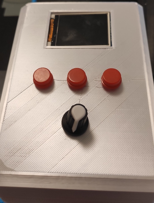
Step 5: Assembly
Now the only thing you have to do is assemble everything together by using 4 M3 screw. Be careful, do nut put the head of the screw into the hole. The screw head will be use as a stand.
Depending on the quality of the print, you may have to use some tools.
After the assembly, make sure that the button is clicky enough.
Step 6: Customize Your Creation !
Now Its time to make it more personal. In my case, i just want to add some stickers but you can do whatever you want.
Step 7: Update/Future Update
Well the sound mixer work great but I would like to upgrade it a little.
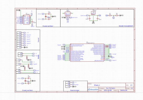
First thing I want to do is make a PCB to look more professional. To do that I used easyEda and I bought it on JLCPCB. As I don’t want to solder all the tiny component I use jclcpb assembly services. It cost me around 15 $ but if you want to do it by yourself it will cost you around 6$
In the future, I will do some upgrade like this one :
- Make the code a lot more customizable
- Rework on 3D model to add some RGB light
- I don’t have others idea
Source: Arduino & TFT Screen Volume Mixer