
Summary of Arduino Sound Effect With Game Handle
This article describes a CU Boulder ATLS 3300 project where push buttons trigger buzzer sounds representing musical tones. The system features two modes controlled by a switch: Mode-1 selects specific tones via buttons, while Mode-2 adjusts sound frequency using a game handle. LEDs indicate the active mode. The build involves connecting five buttons, four buzzers, two LEDs, a switch, and an Arduino Uno with various resistors and wires to create a functional musical interface housed in a cardboard enclosure.
Parts used in the Arduino Sound Effect With Game Handle:
- Wires
- Button * 5
- LED * 2
- Switch * 1
- Buzzer (low-level trigger) * 4
- Resistor * 8
- Arduino Uno * 1
- Game handle
- Cardboard for enclosure
This project is for the class ATLS 3300 at CU Boulder.
Push buttons can make buzzers sound.
Five buttons represented the tone C, D, E, F, G.
There are two modes.
The switch determines the mode and LEDs can indicate which mode we are in.
In mode-1, the game handle can determine which buzzer sound.
In mode-2, the game handle can change the frequency of the sound.
Material:
wires
Button * 5
LED * 2
Switch * 1
Buzzer (low-level trigger) * 4
Resistor * 8
Arduino Uno * 1
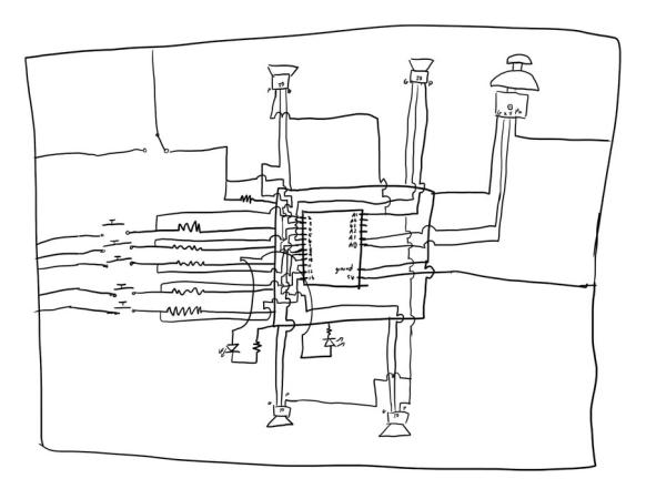
Step 1: Schematic
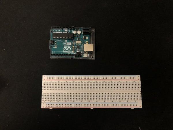
Step 2: Hardware 1:
Step 3: Hardware 2:
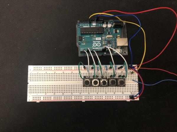
Add 5 buttons to the board.
Connect Them to the 5v power and ground them with resistors.
Parallel them with digital input on the Arduino (using the port without PWM).
I’m using the port 2,4, 7, 12, 13 for the button 1,2,3,4,5.
Step 4: Hardware 3:
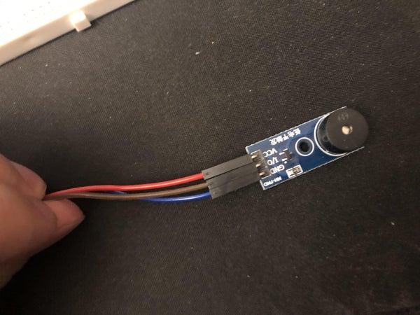
Connect buzzer to the board.
VCC to v5, GND to ground, and I/O to the PWM output on the Arduino.
I’m using 3~, 5~, 6~, 9~ on the Arduino for the buzzer 1,2,3,4.
Step 5: Hardware 4:
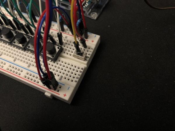
Add switch to the breadboard.
Power the middle needle with 5v and ground the left needle with a resistor.
Parallel the resistor with input on Arduino.
I’m using port 8 on the Arduino for the switch.
Step 6: Hardware 5:
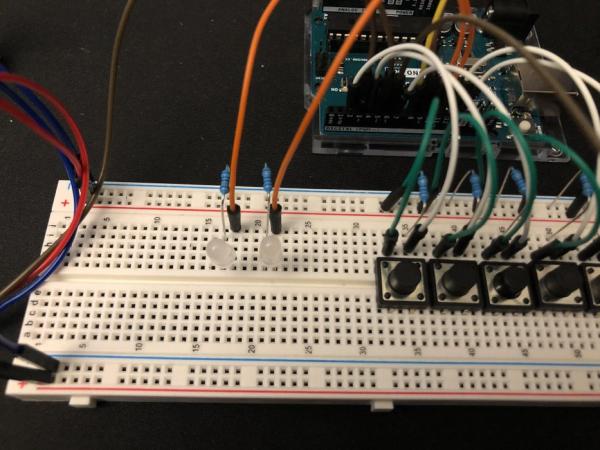
Add two LEDs to the breadboard.
Ground them with a resistor.
Connect them with outputs on the Arduino.
I’m using ports 10 and 11 for LEDs 1 and 2.
Step 7: Hardware 6:
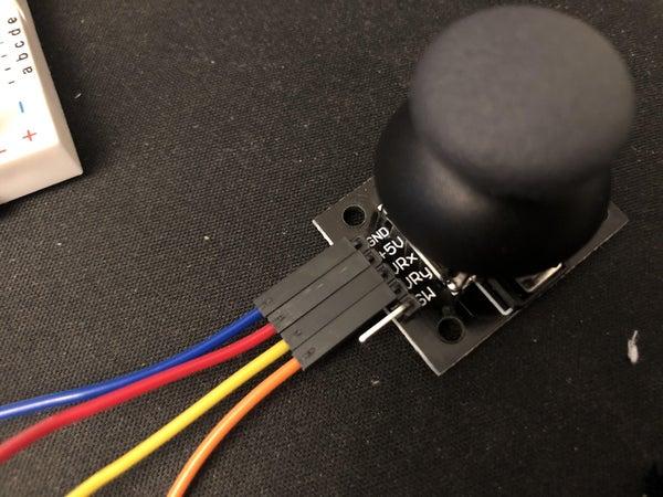
Connect GND, + 5V, VRx, and VRy to the ground, 5v, A0, and A1 on the Arduino.
Step 8: Step 7: Add Enclosure
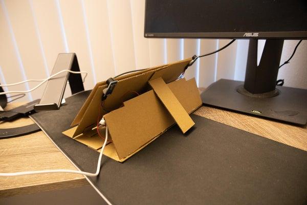
Using cardboard making an enclosure for the project.
Step 9: Code 1:
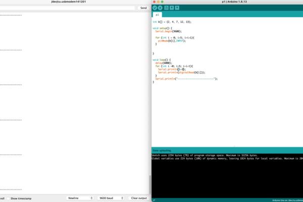
Test the button.
If everything looks good, change the testing code to the reading code.
Step 10: Code 2:
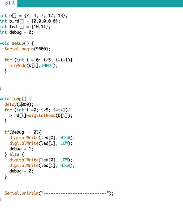
Test the LEDs.
If the LEDs can light up separately, link the Leads to the mode indicator.
Source: Arduino Sound Effect With Game Handle
- What components are required for the project?
The project requires wires, five buttons, two LEDs, one switch, four low-level trigger buzzers, eight resistors, an Arduino Uno, a game handle, and cardboard. - How many buttons represent musical tones?
Five buttons represent the tones C, D, E, F, and G. - How does the system determine the active mode?
A switch determines the mode, and two LEDs indicate which mode is currently active. - What happens in mode-1 of the device?
In mode-1, the game handle determines which buzzer sound is played. - What function does the game handle serve in mode-2?
In mode-2, the game handle changes the frequency of the sound. - Which Arduino ports are used for the five buttons?
Ports 2, 4, 7, 12, and 13 are used for button 1 through button 5. - How are the buzzers connected to the Arduino?
VCC connects to 5V, GND to ground, and I/O connects to PWM outputs on the Arduino. - What Arduino port is assigned to the mode switch?
Port 8 on the Arduino is used for the switch input. - Which ports control the two LEDs?
Ports 10 and 11 are used for LED 1 and LED 2 respectively. - How is the final project enclosed?
The project uses cardboard to make an enclosure.
