Summary of Arduino Solar Cell Tester
This article details the construction of a handheld Arduino-based Solar Cell Tester designed to measure voltage, current, and power of scavenged solar cells outdoors. The device solves the inefficiency of traditional breadboarding by providing accurate readings up to 15V and 1A using a voltage divider and parallel power resistors for current sensing. It features a serial LCD display, toggle switches for circuit selection, and runs on AAA batteries, allowing users to quickly test individual or grouped cells in various configurations without external lab equipment.
Parts used in the Arduino Solar Cell Tester:
- Arduino Uno
- Arduino Proto Shield (Adafruit #51)
- White Enclosure for Arduino (Adafruit #271)
- Parallax Serial LCD Panel (Parallax #27977)
- 10 ohm 10W Power Resistors (Radio Shack #271-132)
- 2K ohm resistor
- 1K ohm resistor
- DPDT Sub-Mini Toggle Switch (Radio Shack #275-614)
- SPDT Slide Switch (Radio Shack #275-409)
- 1/8" Phone Jack (Radio Shack #274-251)
- 1/8" Phone Plug (Radio Shack #274-284)
- 14" Insulated Test Leads (Radio Shack #278-1156)
- AAA Battery Holders (2 cell holder) (Radio Shack #270-413)
When I’m building Solar Shrubs and other solar-powered creations, I often scavenge cells from various off-the-shelf devices such as solar garden or security lights. But these cells are rarely labeled as to their voltage, current, and power output.
So it’s off to my bread-boarding station. First, I put each cell under a lamp and connect it to my multimeter to get the volts. Then I build an I-R curve by measuring the voltage across a series of different sized resistors. This takes a lot of time and effort and I still don’t know what the values are in sunlight. I could drag the multimeter, breadboard, and all associated components outside, but that would be a hassle and it’s still very time consuming if I have a lot of cells to test.
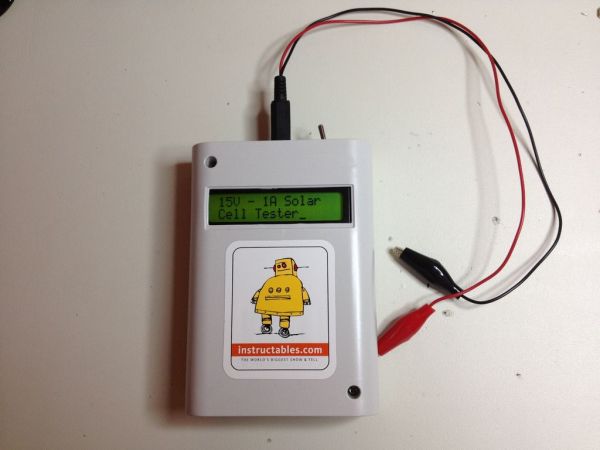
My solution was to build an Arduino-based, handheld Solar Cell Tester. This tester can read up to 15 Volts at 1 Amp. Now I can carry one device outside, attach a single solar cell or a group of cells in series or parallel, and read voltage, current, and power quickly and accurately!
Here’s how you can build one too!
NOTE: At first glance this device looks very similar to Ladyada’s impressive Portable Solar Charging Tracker, But mine is actually more limited; only testing the cells, not lithium batteries and charging circuits. I used Adafruit’s enclosure and protoshield for this project, but the calculations, circuits, and program are all mine (except for the excellent help, as always, from the Arduino on-line community!)
Step 1: Materials & Tools Needed
Materials Used:
(1) Arduino Uno
(1) Arduino Proto Shield (Adafruit #51)
(1) White Enclosure for Arduino (Adafruit #271)
(1) Parallax Serial LCD Panel (Parallax #27977)
(2) 10 ohm 10W Power Resistors (for current sensing circuit) (Radio Shack #271-132)
(1) 2K ohm resistor (for voltage sensing circuit)
(1) 1K ohm resistor (for voltage sensing circuit)
(1) DPDT Sub-Mini Toggle Switch (Radio Shack #275-614)
(1) SPDT Slide Switch (Radio Shack #275-409)
(1) 1/8″ Phone Jack (Radio Shack #274-251)
(1) 1/8″ Phone Plug (Radio Shack #274-284)
(2) 14″ Insulated Test Leads (Radio Shack #278-1156)
(2) AAA Battery Holders (2 cell holder) (Radio Shack #270-413)
Tools Needed:
Soldering Iron
Solder
Helping Hands
Wire strippers
Side cutters
Dremel
Step 2: The Circuits
A DPDT toggle switch (SW1) serves as the on-off control which disconnects the 4-AAA batteries from the Arduino as well as the “Cell Under Test” from the sensing circuits. The cell under test is connected via red and black test leads attached to a phone plug and plugged into a 1/8″ phone jack on top of the tester.
The tester includes two sensing circuits; one for measuring voltage and one for measuring current. A SPDT toggle switch (SW2) connects the cell under test to these circuits individually.
The Voltage Circuit: The Arduino analogRead command reads voltage up to +5V and returns an integer between 0 and 1023. In order for the tester to read up to 15V, you’ll create a voltage divider that consists of a 2K (R3) and 1K (R4) resistor. The voltage across R4 is one-third the source voltage so it can read 0-15V. (NOTE: You can use any two resistors with a 2 to 1 ratio).
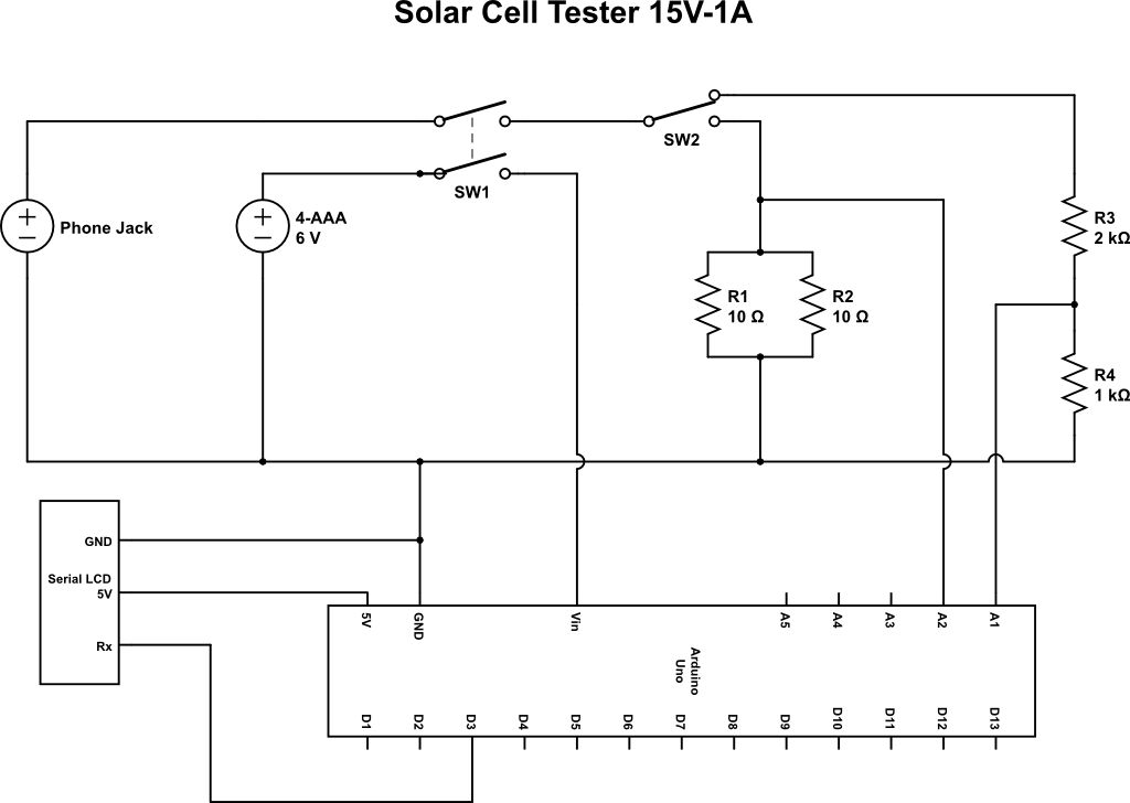
The Current Circuit: Since the analogRead command returns a value of 0-1023 (for a max of 5V), each unit is 5 divided by 1024 or 4.9mV. And from Ohms law, we know that the voltage drop across a resistor is equal to the current times the resistance. So the voltage drop across a 4.9 ohm resistor with 1mA of current is 4.9mV. This means we can effectively read the current across a 4.9 ohm resistor using the actual value returned by the analogRead command. There are at least two problems with this strategy.
(1) Because of it’s low resistance, this circuit can produce a high current and consequently too much power for standard 1/4 or 1/2 Watt resistors. They would become dangerously hot very fast. So I recommend using Power resistors with at least a 5W rating.
(2) I looked high and low and couldn’t find a 4.9 ohm power resistor.
The Solution? Connect two 10 ohm resistors in parallel, which will give you approximately 5 ohms (close enough for this project). The power resistors I used are rated at 10W so they’ll stay nice and cool in this circuit.
The voltage, current, and power readings will be displayed on a 2×16 character serial LCD panel. You can use any LCD panel, but the wiring and program may need to be modified to accommodate it.
(1) Arduino Proto Shield
(1) White Enclosure for Arduino
(1) Parallax Serial LCD Panel
(2) 10 ohm 10W Power Resistors
For more detail: Arduino Solar Cell Tester
- What is the primary purpose of this project?
To build a handheld device that reads voltage, current, and power of solar cells quickly and accurately outdoors. - How does the tester measure voltages up to 15 Volts?
It uses a voltage divider consisting of a 2K and 1K resistor to scale the input so the Arduino can read it. - Can this device charge lithium batteries?
No, it is limited to testing cells only and does not handle lithium batteries or charging circuits. - Why are 10 ohm 10W power resistors used instead of standard resistors?
Standard resistors would become dangerously hot due to high current; the 10W rating keeps them cool. - How is the current sensing circuit configured?
Two 10 ohm resistors are connected in parallel to create an effective resistance of approximately 5 ohms. - What components are required to power the device?
The device is powered by two AAA battery holders containing four AAA batteries. - Does the device support testing multiple cells at once?
Yes, it can attach a single solar cell or a group of cells connected in series or parallel. - What type of display is used to show the readings?
A 2x16 character serial LCD panel displays the voltage, current, and power readings.