Summary of Arduino and Soil Moisture Sensor
This article explains interfacing the FC-28 soil moisture sensor with an Arduino in both analog and digital modes. It describes how the sensor uses two probes to measure soil conductivity (thus moisture), gives specifications and pinout (VCC, A0, D0, GND), mentions an onboard potentiometer and LM393 comparator for digital thresholding, and provides wiring for analog mode (VCC→5V, GND→GND, A0→A0) with analog readings mapped 0–1023 to 0–100% for display and pump control.
Parts used in the Soil Moisture Sensor and Arduino Interface:
- Soil moisture sensor FC-28 module
- Arduino board (compatible with 3.3–5V logic)
- Wires/jumper cables
- Soil (for testing)
- Optional water pump (for control based on moisture)
- Power source for Arduino (5V)
In this article, we are going to interface a Soil moisture sensor FC-28 with Arduino. This sensor measures the volumetric content of water inside the soil and gives us the moisture level as output. The sensor is equipped with both analog and digital output, so it can be used in both analog and digital mode. In this article, we are going to interface the sensor in both modes. So let’s begin our tutorial on interfacing Arduino and Soil moisture sensor.
Working of Sensor
The soil moisture sensor consists of two probes which are used to measure the volumetric content of water. The two probes allow the current to pass through the soil and then it gets the resistance value to measure the moisture value.
When there is more water, the soil will conduct more electricity which means that there will be less resistance. Therefore, the moisture level will be higher. Dry soil conducts electricity poorly, so when there will be less water, then the soil will conduct less electricity which means that there will be more resistance. Therefore, the moisture level will be lower.
This sensor can be connected in two modes; Analog mode and digital mode. First, we will connect it in Analog mode and then we will use it in Digital mode.
Specifications
The specifications of the soil moisture sensor FC-28 are as follows
| Input Voltage | 3.3 – 5V |
| Output Voltage | 0 – 4.2V |
| Input Current | 35mA |
| Output Signal | Both Analog and Digital |
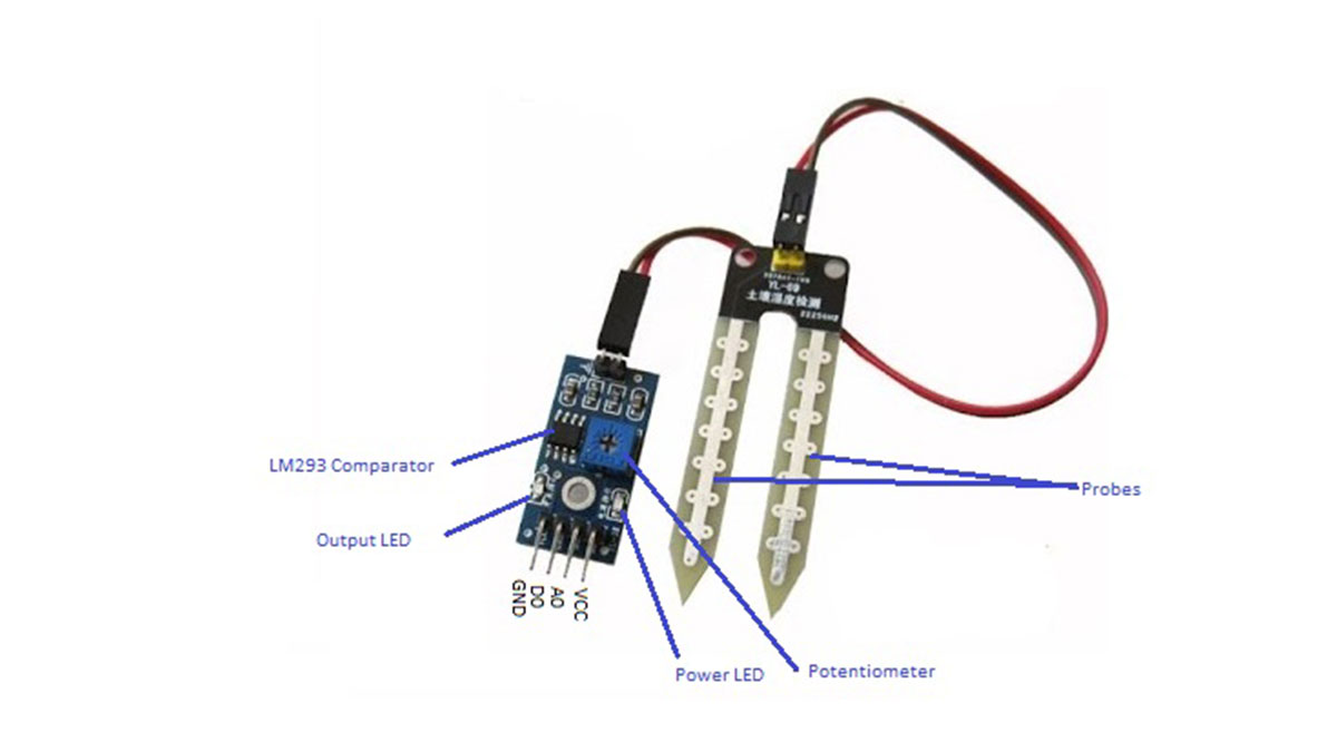
Pin Out – Soil Moisture Sensor
The soil Moisture sensor FC-28 has four pins
- VCC: For power
- A0: Analog output
- D0: Digital output
- GND: Ground
The Module also contains a potentiometer which will set the threshold value and then this threshold value will be compared by the LM393 comparator. The output LED will light up and down according to this threshold value.
Analog Mode – Interfacing Soil Moisture Sensor and Arduino
To connect the sensor in the analog mode, we will need to use the analog output of the sensor. When taking the analog output from the soil moisture sensor FC-28, the sensor gives us the value from 0-1023. The moisture is measured in percentage, so we will map these values from 0 -100 and then we will show these values on the serial monitor.
You can further set different ranges of the moisture values and turn on or off the water pump according to it.
Circuit Diagram
The connections for connecting the soil moisture sensor FC-28 to the Arduino are as follows.
- VCC of FC-28 to 5V of Arduino
- GND of FC-28 to GND of Arduino
- A0 of FC-28 to A0 of Arduino
Read More: Arduino and Soil Moisture Sensor
- What does the FC-28 soil moisture sensor measure?
The FC-28 measures the volumetric content of water in soil by sensing conductivity between two probes. - How does the sensor detect moisture level?
The two probes allow current to pass through the soil; wetter soil conducts more electricity (lower resistance) indicating higher moisture, while dry soil conducts less (higher resistance) indicating lower moisture. - What outputs does the FC-28 provide?
The FC-28 provides both analog (A0) and digital (D0) outputs. - What are the pins on the FC-28 module?
The module has VCC, A0, D0, and GND pins. - What is the input voltage range for the FC-28?
The input voltage range is 3.3 to 5V. - How do you wire the sensor in analog mode to an Arduino?
Connect VCC of FC-28 to 5V on Arduino, GND to GND, and A0 of FC-28 to A0 of Arduino. - What is the analog output range and how is it used?
The analog output gives values from 0 to 1023 which can be mapped to 0–100% moisture and shown on the serial monitor. - What component on the module sets the digital threshold?
An onboard potentiometer sets the threshold which is compared by the LM393 comparator to produce the digital output and LED indication.