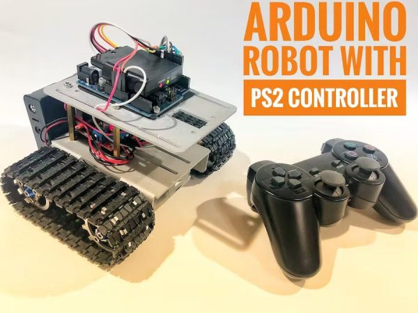
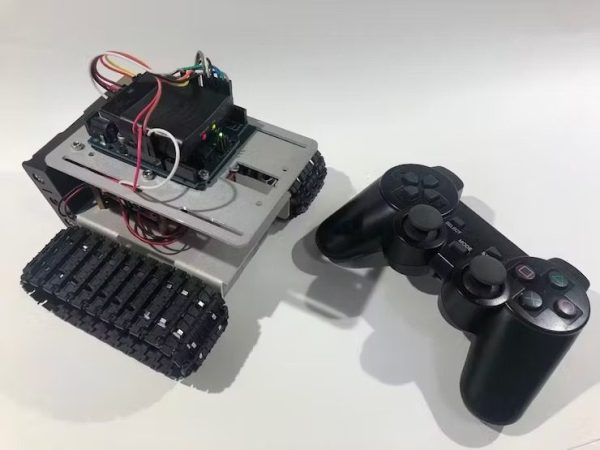
Summary of Arduino Robot With PS2 Controller (PlayStation 2 Joystick)
Summary: This tutorial explains how to build a robotic tank controlled by a wireless PlayStation 2 controller and an Arduino Uno. It covers required tools and materials, assembly of a tank chassis, wiring the Arduino, L298N H-bridge and PS2 receiver, installing the PS2X Arduino library, and two example sketches: D-pad binary control and analog-stick throttle/steering with L2/R2 for forward/reverse.
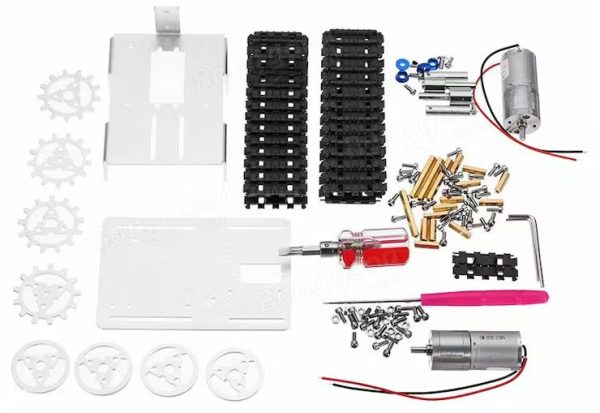
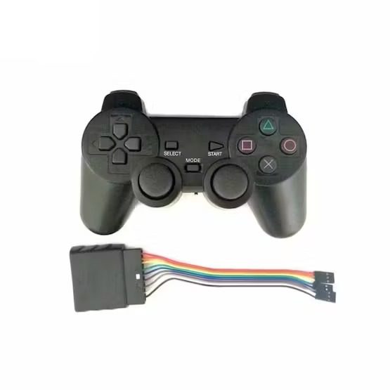
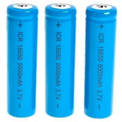
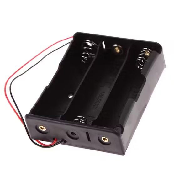
Parts used in the Robotic Tank with PS2 Controller:
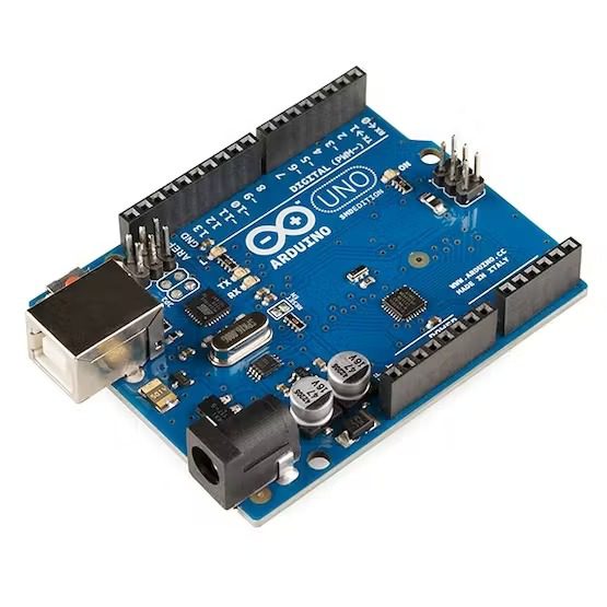
- Arduino Uno based dev board
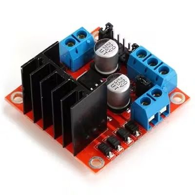
- L298N dual channel H-bridge module
- DIY Robot Chassis Tank kit (with two DC motors, gears, tracks, bolts, nuts)
- PS2 Wireless Remote Control and receiver
- 18650 3.7V batteries (x3)
- 3S 18650 battery holder
- 18650 battery charger
- Jumpers (male-female and male-male)
- Type-B USB cable
- Soldering iron and wire
- EVA foam sheet (or other non-conductive material)
- Double sided tape
- Scissors
In this tutorial, I’ll show you how to use a wireless PlayStation 2 (PS2) controller and an Arduino Uno pilot a robotic tank.
Story
An Arduino Uno board was used at the core of this project. It receives commands from the wireless controller and sets the speed of the motors. Other development boards might also be used (NodeMCU, Firebeetle, etc.), and the principles presented in this tutorial can be applied on other models of robots and gadgets.
I’ve previously designed a Blynk controlled robotic tank PS2. It connects to a Wi-Fi network and receives commands from Blynk server. A smartphone running Blynk app was used as a remote control, and different input methods were used: push buttons, sliding bars and even smartphone’s accelerometer. You can find more about this project here: https://www.hackster.io/igorF2/wi-fi-controlled-robot-using-wemos-d1-esp8266-and-blynk-464198
I’ve also made some experiments with voice commands. It might be usefull if you want to remotelly control a robot without using your hands, or if you want to made it accessible for someone with limited movements. One might think of a robotic voice controlled wheel chair, for instance. A DIY robotic kit was used, along with some of my favourite tools: Adafruit.io, IFTTT and Arduino IDE. Full instructions here:
https://www.hackster.io/igorF2/wi-fi-voice-controlled-robot-using-google-assistant-79802c
You can use different kits or even desing your own robots using simple materials, without the need of using complex tools such as 3D printers and laser cutting machines. You can find an example on one of my previous tutorials:
https://www.hackster.io/igorF2/widc-wi-fi-controlled-fpv-robot-8f1e09
Step 1: Tools and Materials
The following tools were used in this project:
Solder iron and wire
- (link / link). The DC motors already came with wires soldered to its terminals… But it will eventually break and you might have to resolder it. So consider having a good solder iron and wire nearby.
EVA foam sheet
- (or other non-conductive material). The robot chassis I used in this project is made of aluminum, and circuit boards are installed on this metal parts. I used a layer of foam sheet between the boards and the metal plate to avoid possible short-circuits.
Double sided tape
- It was used for glueing the foam sheets to the circuit boards, and for the installation of the H-Bridge module.
- Scissors, for cutting some foam sheet rectangles.
I used the following hardware parts for my project:
Arduino Uno based dev board
- (link / link / link / link). It’s used as the main controller of the robot. It is really easy to use and program with Arduino IDE, great for beginner on electronics and programming.
L298N dual channel H-bridge module
- (link / link / link / link). This module allows the 3.3V signals from the Wemos (or an Arduino) to be amplified to the 12V needed for the motors.
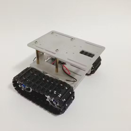
DIY Robot Chassis Tank
- (link). This awesome kit has with everything you need to built a tank: two DC motors, gears, tracks, bolts, nuts, etc. It already comes with the tools need for assembling the chassis, which is great for beginners!
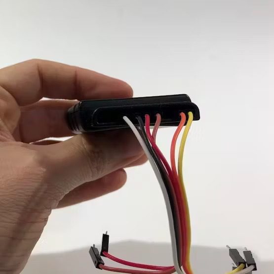
PS2 Wireless Remote Control
- (link). This videogame controller can send commands wirelessly to a receiver, which can be interfaced with an microcontroller using serial communication.
18650 3.7V batteries (x3)
- (link / link). I used to power the whole circuit. This tank uses 12V motors. I used three 3.7V batteries in series for powering them.
3S 18650 battery holder
- (link / link / link). It can hold three 18650 batteries in series, and can be easily be attached to the back of the tank.
18650 battery charger
- (link / link). Your batteries will eventually run out of power. When that happens, a battery charger will come to your rescue.
- Jumpers (link / link). I used 6 male-female jumpers for signals between the h-bridge an the Wemos, and 2 male-male jumpers for 5V and Gnd. You might need more if you plan to add some sensors.
- Type-B USB cable. You’ll need this for uploading your code. Most of the boards already come with its own cable.
The links above are only a suggestion of where you can find the items used in this tutorial (and maybe support my future tutorials). Feel free to search for them elsewhere and buy at your favorite local or online store.
Step 2: Assembling the Robot
The first part of this project was the assembly of the robot structure.
In previous projects I developed the structure of my own robot, using easily accessible materials (without the need for complex tools, 3D printers or laser cutting machines). You can find this project in the link below:
https://www.hackster.io/igorF2/widc-wi-fi-controlled-fpv-robot-8f1e09
Robot Structure
Later I decided to give a chance for a robotic kit obtained from an online store. You can find a link to the robot chassis at the following link: http://bit.ly/2ycI8fP. If you’re looking for a kit, I think it’s a good option! I used it in two other tutorials, as you can see on the links bellow:
https://www.hackster.io/igorF2/wi-fi-controlled-robot-using-wemos-d1-esp8266-and-blynk-464198
https://www.hackster.io/igorF2/wi-fi-voice-controlled-robot-using-google-assistant-79802c
At first it seemed that the assembly would be complex or that I would run into problems like the lack of parts (given the amount of parts that make up the kit). But this kit really surprised me! All the pieces seem to me of good quality, and several spare parts accompanied the kit. Thus, a screw lost underneath the workbench won’t make it impossible to carry out your project, which I found to be excellent (especially after losing a couple of screws).
Another positive point is that all the tools needed to mount the robot are included in the kit (a couple of Allen wrenches and the screwdriver). I believe this makes the kit excellent for starters who doesn’t have lots of tools!
As a negative aspect I would highlight the lack of documentation. The robot’s assembly manual (a spreadsheet file in Chinese) is not extremely user friendly, and there isn’t a lot of tutorials online for that tank. And so I decided to document the process of assembling my robot in the video above! Another point of attention concerns the material of the robot structure. The base is entirely made of aluminum, which can cause some short circuit if the pins of the printed circuit boards touch the frame.
There are other online kits that you can use. You can even maker your own structure, as I described bellow.
Step 3: Wiring Up the Circuit
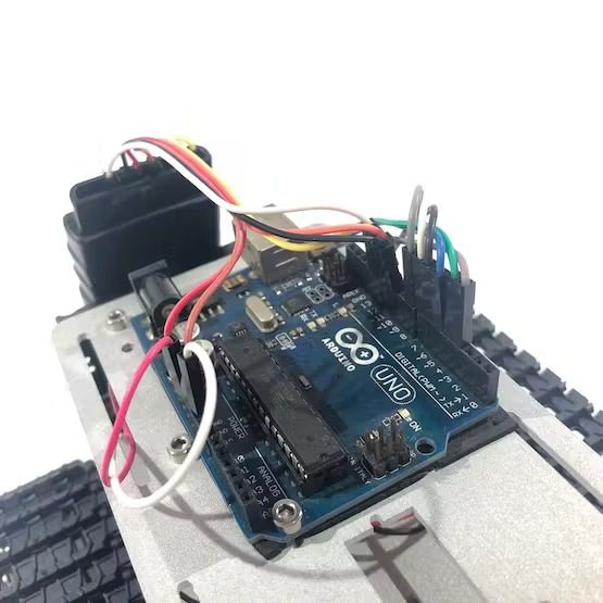
A power pack made of three 18650 batteries was installed on the back of the robot. It provides 11.1V (3 x 3.7V) to the robot. That’s enough to power the 12V DC motors.
A L298N dual channel H-bridge was used for the control of the motors. It receives some 5V signals of the Arduino board, and provide higher voltages for the motors. It also allow the motors to run in both directions, depending on the combination of those input signals.
Each device was connected according to the schematics.
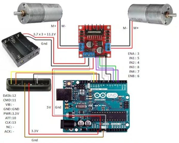
Follows a list of the pins you’ll need to connect:
Arduino Uno inputs/outputs:
- Digital pin 3 => H-Bridge ENA pin
- Digital pin 5 => H-Bridge IN1 pin
- Digital pin 4 => H-Bridge IN2 pin
- Digital pin 8 => H-Bridge IN3 pin
- Digital pin 7 => H-Bridge IN4 pin
- Digital pin 6 => H-Bridge ENB pin
- 5V pin => H-Bridge 5V pin
- Gnd pin => H-bridge Gnd pin
- Digital pin 10 => PS2 receiver pin 6
- Digital pin 11 => PS2 receiver pin 2
- Digital pin 12 => PS2 receiver pin 1
- Digital pin 13 => PS2 receiver pin 7
- 3.3V pin => PS2 receiver pin 5
- Gnd pin => PS2 receiver pin 4
H-Bridge inputs/outputs:
- ENA pin => Arduino digital pin 3
- IN1 pin => Arduino digital pin 5
- IN2 pin => Arduino digital pin 4
- IN3 pin => Arduino digital pin 8
- IN4 pin => Arduino digital pin 7
- ENB pin => Arduino digital pin 6
- 5V pin => Arduino 5V pin
- Gnd pin => Arduino Gnd pin
- Gnd pin => Battery pack negative wire
- 12V pin => Battery pack positive wire
- OUT1 => Right motor negative wire
- OUT2 => Right motor positive wire
- OUT3 => Left motor positive wire
- OUT4 => Left motor negative wire
PS2 receiver:
- Pin 1 (data) => Arduino digital pin 12
- Pin 2 (command) => Arduino digital pin 11
- Pin 4 (ground) => Arduino Gnd pin
- Pin 5 (power) => Arduino 3.3V pin
- Pin 6 (attention) => Arduino digital pin 10
- Pin 7 (clock) => Arduino digital pin 13
Step 4: Setup Arduino IDE

For this project I used Arduino IDE for programming the Arduino board.
1. Download and install Arduino IDE latest version
You can find the latest version for Windows, Linux or MAC OSX on Arduino’s website: https://www.arduino.cc/en/main/software
Download it for free, install it on your computer and launch it.
2. Adding the libraries
In this project, I use Arduino PS2X library.
Download the library at https://github.com/madsci1016/Arduino-PS2X. Unzip the file, and copy the folders to Arduino IDE libraries/tools folders.
…………
Now that your dev environment is ready, let’s move on to the next step!
Step 5: PS2 Wireless Controller Library Explained
A PS2 wireless controller is a great tool for your robotics projects. It has a incredible amount of buttons: 20 digital push buttons and 2 analog sticks. This way, there are endless possibilities to control your robot.
I used Bill Porter’s PS2X library (https://github.com/madsci1016/Arduino-PS2X) to interface the controller to an Arduino Uno board.
It defines a PS2X Class for the controller, which contains some methods for reading analog and digital inputs from the joystick. An object to this class is created using the following code (before or during the setup):
PS2X ps2x;
Once the object was defined, it has to be linked to Arduino I/O pins using the following function:
error = ps2x.config_gamepad(clock,command,attention,data, pressure?, rumble?);
This function might return some errors if there’s something wrong with the connections or with the controller itself.
The main functions used from the library are the ones for reading digital and analog inputs. To read and digital input, the following method is used:
ps2x.Button(button);
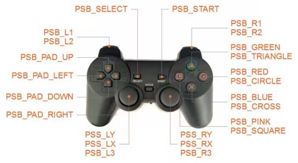
In which button is the name of the button to be read. Each button is maped as follows:
Buttons Actions
Directional buttons:
- PSB_PAD_UP = D-pad up button;
- PSB_PAD_DOWN = D-pad down button;
- PSB_PAD_LEFT = D-pad left button
- PSB_PAD_RIGHT = D-pad right button
Action buttons:
- PSB_GREEN or PSB_TRIANGLE = green triangle button
- PSB_RED or PSB_CIRCLE = red circle button
- PSB_BLUE or PSB_CROSS = blue x button
- PSB_PINK or PSB_SQUARE = pink square button
Triggers:
- PSB_L1 = left side trigger button 1
- PSB_R1 = right side trigger button 1
- PSB_L2 = left side trigger button 2
- PSB_R2 = right side trigger button 2
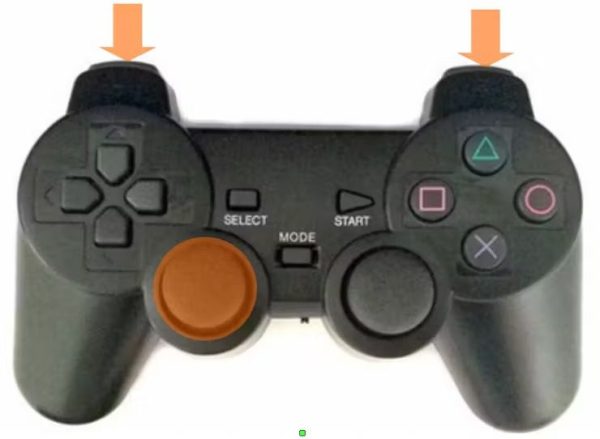
Sticks:
- PSB_L3 = left stick push button (yes, you can press the stick as a push button)
- PSB_R3 = right stick push button
Menu:
- PSB_SELECT = select button
- PSB_START = start button
To read the analog value (with will be converter in a integer between 0 and 255) of the sticks use the following method:
ps2x.Analog(stick_axis);
In which stick_axis represents the stick and the direction to be read, as follows:
- PSS_LY = y-position of left stick
- PSS_LX = x-position of left stick
- PSS_RY = y-position of right stick
- PSS_RX = x-position of right stick
With those basic functions you’ll be ready to use the PS2 controller on your project! On the following steps I show some Arduino sketch examples combining those buttons!
Step 6: Sketch #1 – Dpad Buttons
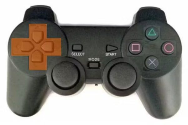
Old video games, such as SEGA Master System and Mega Drive and Nintendo SNES, didn’t have force sensitive buttons. The directional buttons were only on/off buttons. For this first example, I wanted to emulate the kind of controls one would have in old video games of those consoles.
For the this first Sketch I used Dpad buttons as inputs to the robot. Each button was used by the robot to perform one of the basic movements: move forward, turn right, turn left or move back.
Those buttons have binary outputs. This way, the microcontroller will only understand that the buttons were pressed, but won’t understand how hard they were pressed. This way, once a given button is clicked, the motors will run at full speed.
If you connected everything according to my schematics, you’ll have the following outputs:
- PSB_PAD_UP = move forward
- PSB_PAD_DOWN = move back
- PSB_PAD_LEFT = turn left
- PSB_PAD_RIGHT = turn right
As I told before, the motor will move at a fixed speed. When turning left or right, motors will run on oposite directions, so that the robot will turn around its axis.
Arduino Code:
Download the code and open it on Arduino IDE. If you use the same pinout I did, you probably won’t have to change anything on the code (although it might be needed, if the orientation of the motors is different
For uploading the code, select ‘Arduino/Genuino Uno’ board, select the right COM port, plug board on your computer’s USB port and upload the code.
After the upload was complete, unplug the USB cable, and put the batteries. The code will start running and the Arduino board will automatically connect the PS2 joystick. Open serial monitor at first use and check the status of the connection. If it fails to connect with the joystick, there are somethings you should do:
- Reset the Arduino Uno board. Try it several times (for me, it usually works after the third reset);
- Check if the joystick is on (and with charged batteries). The receiver has some LEDs that will indicate if the joystick was paired. Also check if Arduino’s RX and TX pins blink as it receives new commands (and updates the status on the Serial port);
- Check the connections… there might be something wrong in the jumpers between the components.
Code Explained:
In this project I only had to use PS2X_lib.h library. I is added in the beginning of the code.
#include <PS2X_lib.h>
Define the pins of the Arduino connected to the h-bridge. If you use the same connections I did, you’ll have the following configuration. If you choose to use different pins, update this part of the code.
// These are used to set the direction of the bridge driver.
#define ENA 3      //ENA
#define MOTORA_1 4 //IN3
#define MOTORA_2 5 //IN4
#define MOTORB_1 8 //IN1
#define MOTORB_2 7 //IN2
#define ENB 6      //ENB
Some global variables were declared before the setup (p2sx, error, type and vibrate). The first one is a instance of the PS2X class. Error status during the connection will be stored on error integer. Type and vibrate will indicate the type of the controller (DualShock or GuitarHero controller) and if it’s supposed to vibrate upon a given command.
The first thing I did during the setup was to configure I/O pins state (as output) and set enable pins to LOW. This way you’ll disable both motors on start-up, and the robot won’t move randomly while it waits for the rest of the code.
// Configure output pins
pinMode(ENA, OUTPUT);
pinMode(MOTORA_1, OUTPUT);
pinMode(MOTORA_2, OUTPUT);
pinMode(ENB, OUTPUT);
pinMode(MOTORB_1, OUTPUT);
pinMode(MOTORB_2, OUTPUT);

// Disable both motors
digitalWrite(ENA,0);
digitalWrite(ENB,0);
Then I started Serial port communication (useful for debugging the code). Choose an appropriate baudrate and set the same speed on the Serial Monitor.
// Start serial communication
Serial.begin(57600);
Configure the ps2x object
Finally, configure the ps2x object with the pins of the Arduino that were connected to the joystick receiver (clock, command, attention and data respectively). It might return an error (to be displayed on the Serial monitor). The type of the controller will also de displayed (although you probably already know the type of controller you have in your hands at this point :D).
error = ps2x.config_gamepad(13,11,10,12, true, true);   //setup pins and settings:  GamePad(clock, command, attention, data, Pressures?, Rumble?) check for error
// Check for error
if(error == 0){
  Serial.println("Found Controller, configured successful");
 }
else if(error == 1)
  Serial.println("No controller found, check wiring or reset the Arduino");
else if(error == 2)
  Serial.println("Controller found but not accepting commands");
else if(error == 3)
  Serial.println("Controller refusing to enter Pressures mode, may not support it.");
// Check for the type of controller
type = ps2x.readType();
switch(type) {
  case 0:
    Serial.println("Unknown Controller type");
    break;
  case 1:
    Serial.println("DualShock Controller Found");
    break;
  case 2:
    Serial.println("GuitarHero Controller Found");
    break;
  }
During main loop the Arduino will read each D-pad button (UP, DOWN, LEFT and RIGTH) and set the different values for the output pins, in order to move the wheels. After a quick delay, a new loop is started.
The following section shows how to move robot forward if UP button was pressed. MOTORA_1 and MOTORA_2 pins define the direction of the rotation for Motor A. ENA will define if the movement is enabled or not (motor ON/OFF). Notice it is an “analog” output (actually a PWM one). It’s value should be something between 0 and 1023. This will modulate the PWM, and change the average voltage at the output of the h-bridge (between 0 and 12V). If the average voltage is too low, the motor won’t be able to move at all.
// MOVE FORWARD
     if(ps2x.Button(PSB_PAD_UP)) {
        digitalWrite(MOTORA_1,LOW);
        digitalWrite(MOTORA_2,HIGH);
        digitalWrite(MOTORB_1,HIGH);
        digitalWrite(MOTORB_2,LOW);
        analogWrite(ENB, 1023);
        analogWrite(ENA, 1023);
        Serial.println("Move forward");
      }
*I used PWM outputs for the ENA and ENB pins. This way, 1023 would represent a pulse with the greatest lenght (pin always on) and 0 the absence of pulses (pin always off). If a different (smaller) value is used here, the motors are expected to run slower, since the average voltage in their terminals will be smaller.
Step 7: Sketch #2 – Analog Stick and Digital Buttons (L2 and R2)
At a given time, all consoles adopted joysticks with two analog sticks. Those new inputs allowed force sensitive inputs that created variable speed actions and became popular in every kind of video games.
In this second example I wanted to use an analog switch for steering the tank, and a pair o push buttons as throttle and brakes/reverse. This kind of configuration is very popular in lots of racing games, like Mario Kart for instance. Press R2 button for acceleration of the tank, L2 for reverse and set the direction of the movement based on x-position of left stick.
The kind of robotic kit I used doesn’t have a lot of inertia (if the voltage on the motors is set to 0V it won’t keep moving for a while). This way, there was no need to define a command for braking the robot.
Most of the code was already explained in previous step. One difference is that I defined two variables that store the speed of each motor (from 0 to 1023).
int motor_right_speed = 0;<br>int motor_left_speed = 0;
Main loop
In the Main loop, the Arduino will read x-position of the left stick. It will receive a value between 0 and 255 and map it between -1023 and 1023.
This value will be added (or subtracted) to the speed of each motor, in order to create a difference between the speed of each track and make the robot turn left or right.
int nJoyL = ps2x.Analog(PSS_LX); // read left stick
nJoyL = map(nJoyL, 0, 255, 1023, -1023);
motor_right_speed = 1023;
motor_left_speed = 1023;
if (nJoyL < 0) {
   motor_right_speed = motor_right_speed + nJoyL;
}
if (nJoyL > 0) {
   motor_left_speed = motor_left_speed - nJoyL;
}
If R2 button is pressed, the tank shall move forward. This way, the Arduino set appropriate values for the motor pins. ENA and ENB create ‘analog’ outputs to each motor, with a value proportional to the speed desired for each motor (based on x-position of left stick).
L2 will do something similar, but reverse the direction of the motor.
if(ps2x.Button(PSB_R2)) {
      digitalWrite(MOTORA_1,LOW);
      digitalWrite(MOTORA_2,HIGH);
      digitalWrite(MOTORB_1,HIGH);
      digitalWrite(MOTORB_2,LOW);
      analogWrite(ENA, motor_right_speed);
      analogWrite(ENB, motor_left_speed);
}
if(ps2x.Button(PSB_L2)) {
      digitalWrite(MOTORA_1,HIGH);
      digitalWrite(MOTORA_2,LOW);
      digitalWrite(MOTORB_1,LOW);
      digitalWrite(MOTORB_2,HIGH);
      analogWrite(ENA, motor_right_speed);
      analogWrite(ENB, motor_left_speed);
}
if(!ps2x.Button(PSB_L2) && !ps2x.Button(PSB_R2)) {
      analogWrite(ENA, 0);
      analogWrite(ENB, 0);
}
Source: Arduino Robot With PS2 Controller (PlayStation 2 Joystick)
- What is the main controller used in the project?
The Arduino Uno based dev board is used as the main controller. - Can the PS2 wireless controller read analog stick values?
Yes, the PS2X library's Analog method returns stick positions as values between 0 and 255. - How are the motors driven to provide higher voltage?
The L298N dual channel H-bridge module amplifies Arduino signals to the motor supply voltage and allows bidirectional motor control. - What battery configuration is used to power the motors?
Three 18650 3.7V batteries in series (3S) provide about 11.1V to power the 12V DC motors. - Which Arduino pins are used for the PS2 receiver connection?
PS2 receiver pins connect to Arduino digital pins: data->12, command->11, attention->10, clock->13, power->3.3V, ground->Gnd. - How does the D-pad control sketch operate the robot?
The D-pad buttons act as binary inputs; UP/DOWN/LEFT/RIGHT map to move forward/back and turn left/right, running motors at fixed PWM speed. - How does the analog stick plus L2/R2 sketch control speed and steering?
The left stick X is read and mapped to adjust left and right motor speeds; R2 accelerates forward and L2 reverses, with PWM used for speed control. - What library is required to interface the PS2 controller?
The Arduino PS2X library (Bill Porter / madsci1016 GitHub) is used to interface the PS2 controller. - What precautions are suggested for mounting PCBs on the aluminum chassis?
Use an EVA foam sheet between circuit boards and the aluminum frame to avoid possible short circuits. - What should you do if the Arduino fails to connect to the PS2 controller initially?
Reset the Arduino several times, check the controller power and pairing LEDs, verify RX/TX activity, and check wiring connections.