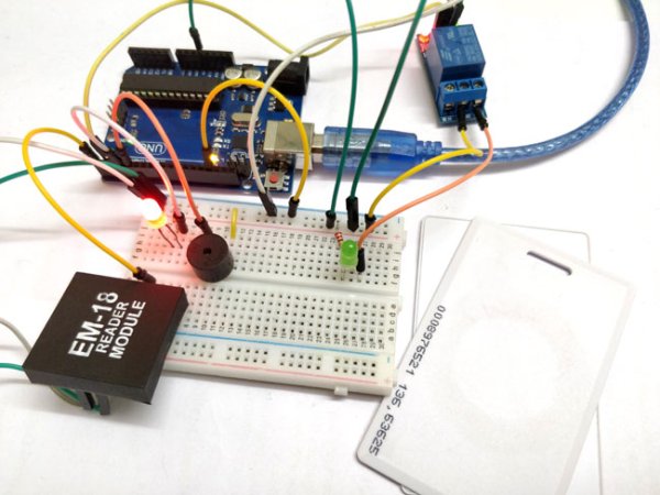
You have seen RFID Door Lock Mechanism in some Hotels and other places, where you don’t need a key to unlock the room. You are given a card and you just need to put it in front of a RFID Reader box, and the lock gets unlocked with a Beep and a Blink of LED. This RFID Door Lock can be made easily at your home and you can install it in any door. These Door lock is just electrically operating door lock which gets open when you apply some voltage (typically 12v) to it.
Here in this project we are using Arduino and relay to trigger the Electric Door Lock and RFID to authenticate, so your RFID tag will act as a key. If you place wrong RFID card near RFID reader a buzzer will beep to alert about wrong card. If you are new to RFID first read its working an interfacing with Arduino.
Material Required:
- Arduino UNO
- EM-18 Reader Module with Tags
- Relay 5v
- LED
- Buzzer
- Connecting wire
- Resistors
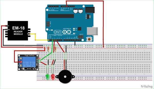
Arduino RFID Door Lock Circuit Diagram
EM-18 RFID Reader:
RFID stands for Radio Frequency Identification. Each RFID card has a unique ID embedded in it and a RFID reader is used to read the RFID card no. EM-18 RFID reader operates at 125 KHz and it comes with an on-chip antenna and it can be powered with 5V power supply. It provides serial output along with weigand output. The range is around 8-12cm. serial communication parameters are 9600bps, 8 data bits, 1 stop bit. This wireless RF Identification is used in many systems like
Check all the RFID Projects here.
The output provided by EM-18 RFID reader is in 12 digit ASCII format. Out of 12 digits first 10 digits are card number and the last two digits are the XOR result of the card number. Last two digits are used for error checking.
For example, card number is 0200107D0D62 read from the reader then the card number on the card will be as below.
02 – Preamble
00107D0D = 1080589 in decimal.
62 is XOR value for (02 XOR 00 XOR 10 XOR 7D XOR 0D).
Hence number on the card is 0001080589
Code and Explanation:
The complete RFID Door Lock Arduino Code is given at the end of this project.
In the below code, the RFID tag number are stored in the “char tag”. “180088F889E1” is my RFID tag number stored in the microchip of the Transponder. The length of the tag number is 12 we have defined the array like “char input [12]”, 12 defines the no. of character or size of array.
char tag[] ="180088F889E1";
char input[12];
int count = 0;
boolean flag = 0;
For find the tag no. of your Arduino you can refer this article.
Now, in below code, we setup the pins of the Arduino UNO board for the operation and the serial.begin() is used for the serial data transmission. Here the pin 2 is used for the relay operation, pin 3 is for the standby red LED and pin 4 is for the buzzer.
Read more: Arduino RFID Door Lock


