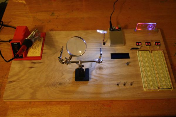
This is a relatively inexpensive and easy to build project that will help you test out all of your Arduino projects and prototypes. Since it has a plug-in power source, it eliminates frequent battery use and leaves the breadboard free of voltage regulators and capacitors providing more room for projects. However, if you need battery power instead, the Prototyping Center also has the option of switching to 9 volts of battery power. Additionally, this prototyping center will have room for a soldering iron and “Third Hand” soldering tool so everything you need will be at your fingertips. The Prototyping Center will give you access to chose from 9 volts, 5 volts (perfect for Arduino prototyping), and 3.3 volts.
A soldering Iron, cordless drill, coping saw, wood glue, hot glue gun, X-Acto knife, and wire cutters are needed.
Step 1: Materials
Major Components in Project
I bought most of the components from Jameco and Tayda Electronics. Tayda is a good choice when buying resistors, LEDs, chrystals, switches and other small, cheap components. I always purchase the more expensive parts from Jameco such as breadboards, integrated circuits, and power supplies. I purchased the wood needed for the base of the project and the acrylic sheet from Lowe’s. Altogether, the cost of the electronic parts should be under $100. The wood and acrylic should be under $15.
1. Plenty of Resistors: Any from 100-500 Ohms should be sufficient. (I bought most of mine from Tayda)
2. Large Breadboard:
http://www.jameco.com/webapp/wcs/stores/servlet/Product_10001_10001_20723_-1 (Like me, if you want a bigger breadboard to work with, consider buying two of these to put together.)
3. Small Breadboard:
http://www.jameco.com/webapp/wcs/stores/servlet/Product_10001_10001_20601_-1
4. LED’s: (At least one red, one blue, and one clear.) http://www.taydaelectronics.com/leds/led-5mm-blue-water-clear-ultra-bright.html
5. Wire: (I bought wire from Jameco)
6. 7-segment LED Display: (6 are needed for this project) http://www.jameco.com/webapp/wcs/stores/servlet/Product_10001_10001_24782_-1
7. 2.1mm Wall Adapter: DCU090050E2961: JAMECO RELIAPRO: Power Supplies & Wall Adapters
8. Breadboard Power Supply: DFR0140: DFROBOT: Education & Hobby Kits
9. 9V Battery Connector: http://www.taydaelectronics.com/9v-9-volt-battery-clip-connector.html
10. Connectors: Cable mount: 08-65-0805: MOLEX INC.: Interconnects Headers: 22-29-2021: MOLEX INC.: Interconnects Housing: 22-01-2027: MOLEX INC.: Interconnects
11. Magnet Reed Sensor: MP201701: CHERRY CORPORATION: Electromechanical
12. Switches: Mini Toggle Switch SPDT On-Off-On
13. Wood (Bottom: 1x3x8): Shop 1 x 3 x 8 Kiln-Dried Whitewood Softwood Board at Lowes.com
14. Wood (Top: 1/4x2x2): Shop 1/4 x 2 x 2 Birch Plywood at Lowes.com
15. Acrylic Sheet: Shop OPTIX 10-in x 8-in Clear Acrylic Sheet at Lowes.com
16. Glue: Both wood glue and hot glue.
17. Rubber Feet: BS01RCL10X20RP: JAMECO VALUEPRO: Electromechanical
18. Small Magnet: I just found one lying around but here’s a link to some small rare earth magnets from Jameco: http://www.jameco.com/webapp/wcs/stores/servlet/Product_10001_10001_2181319_-1
If you don’t already have one, here’s the link to a Third-Hand Tool from Jameco: 3RD HAND: JAMECO BENCHPRO: Test, Tools & Supplies.
Step 2: Building the Base
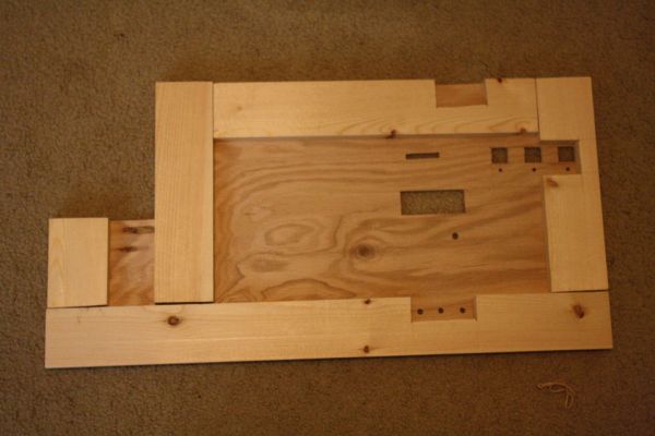
Refer to the 2nd picture to get an idea of where each hole should be cut.
1. For the top of the base of the prototyping center I cut out a 2×1 foot sheet of the plywood. The upper left-hand corner was cut out for the soldering iron.
2. To display each of the three voltages, two of the 7-segment LED displays must be hot glued together (for example, in one pair, one display will light up “9” and the other “V” forming a single display that shows “9V”). Make sure the hole is cut big enough for the leads of both LED displays to fit through. When measured put together, the 7-segment LED displays are 0.75×0.75 inches. Using a drill and coping saw, cut three holes just under 0.75×0.75 inches so that the displays will rest on top of the wood surface. However, make sure to cut the holes big enough so that the display’s leads will fit through the hole.
3. Below each of the holes cut for the three displays, drill a hole for the power supply header. Again, make sure the hole is small enough so that the component rests on top of the wood but big enough so that the leads fit through the hole.
4. Near the bottom of the base, or wherever you chose to put them, drill two holes for the switches. (I drilled three because I have an extra switch for an LCD screen I will use in a later project.)
5. Also, cut a long, thin hole just below where the small breadboard with the power supply will be. This will allow wires from displays and LEDs underneath the base to reach the voltage on the small breadboard.
6. I decided to put a light just to the left of the smaller breadboard for extra lighting when soldering. You can use a clear LED but I found a broken part of an old LCD screen that worked perfectly as a lamp.
7. Drill a hole about an inch to the left of where the 9V header will be. This is where the wires of the magnet sensor will come through (see picture 3).
8. Finally, drill two holes in the top right hand corner of the base. These will be for the LEDs that light up the acrylic display. You might want to wait to drill these holes until after the bottom section of the base is glued on.
After you finish cutting and drilling all the holes for the top of the base, begin measuring and gluing on the bottom pieces. Follow picture 5. Place the rubber feet under each corner of the base. This will give it a strong grip on the work surface.
Islamic Center of Reseda, California
For more detail: Arduino Prototype Center