Summary of STEAMPUNK STEAM GAUGE, POWERED BY ARDUINO
This project transforms a vintage Ashcroft pressure gauge into a dynamic, steampunk-style wall decoration featuring moving parts and blinking lights. The creator repurposed the gauge's internal "C" shaped Bourdon tube mechanism, integrating an Arduino-controlled continuous rotation servo to simulate pressure flexing. The build required diverse skills including metalworking, circuit design, woodworking, and electrical wiring to create a unique, powered mechanical display for a kitchen space.
Parts used in the Steampunk Steam Gauge:
- Ashcroft 10 inch pressure gauge
- Continuous rotation servo
- Bourdon tube (internal mechanism)
- Brass outer ring
- Pointer shaft
- Faceplate screws
- Arduino microcontroller
- Circuit components
- Wood for mockups and decoration
This was created to be some eye-candy for my kitchen. I wanted something unique for a special blank space on my wall, and adding movement, blinky lights and interesting mechanical “guts” made it even better.
Ultimately, this project ended up requiring the following range of skills:
1. Basic mechanical skills
2. Light metalworking and fabrication
3. Graphic design – for the new dial face
4. Circuit design
5. Arduino programming
6. Woodworking- for mockups and decoration
7. Drywall and 120V wiring – for mounting and permanent power supply
Step 1: Video

Step 2: IN THE BEGINNING: A FIRST LOOK INSIDE
This project started with a beat-up Ashcroft 10″ pressure gauge bought cheap on ebay. The glass dial cover was cracked and the valve was frozen, but that didn’t matter. The main priority was size, because ideally I would want to add stuff inside it. If the mechanical guts of the instrument were “interesting” enough, then I would also want to make those visible as well.
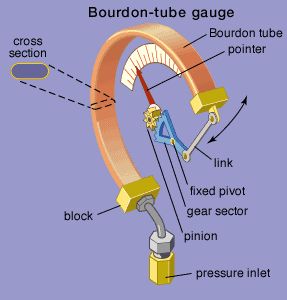
Fortunately, the three screws holding the brass outer ring were not frozen or stripped. The pointer came off with just a little persuasion, as it was simply press-fit onto the shaft. The faceplate was also held in with three screws, all of which came out as well. The insides had the standard “C” shaped Bourdon tube, which flexes open under pressure. The mechanism was in good shape overall, but it would need some cleaning up and polishing. So far so good….
Step 3: THE BASIC MECHANISM
A closer look at the mechanism.
Step 4: THE CHALLENGE OF MOTION – part 1
It could have been a static decoration, but if at all possible I wanted it to be dynamic, but I had to overcome some issues first………
Without steam pressure to create flex, the Bourdon tube is essentially a stiff “C” shaped spring. While it can be flexed open by hand, and thereby creating the desired dial pointer movement, the force necessary to do so is not insignificant. Adding to the challenge, the space available inside the gauge for mounting some type of actuator is limited. I was able to determine that a continuous rotation servo would fit in the space between the Bourdon tube and case. This shows the servo’s final mounting configuration. Details on how and why exactly that spot are in later steps, but suffice to say that there was just enough room to make it work.
** SEE STEP 12 FOR A VIDEO OF THE COMPLETED MECHANISM IN ACTION**
For more detail: STEAMPUNK STEAM GAUGE, POWERED BY ARDUINO
- What was the primary reason for selecting this specific pressure gauge?
The main priority was the size, as it allowed enough room to add internal components. - How did the author overcome the challenge of limited space inside the gauge?
A continuous rotation servo was determined to fit in the space between the Bourdon tube and the case. - Can the Bourdon tube be flexed manually without steam pressure?
Yes, it can be flexed open by hand, though the force necessary is not insignificant. - What skills were required to complete this project?
The project required basic mechanical skills, light metalworking, graphic design, circuit design, Arduino programming, woodworking, and drywall with 120V wiring. - Why was the cracked glass dial cover considered acceptable initially?
The cracked glass did not matter because the main priority was the size and the potential to make the mechanical guts visible. - How was the pointer removed from the original instrument?
The pointer came off with just a little persuasion as it was simply press-fit onto the shaft. - What type of motor was chosen to drive the mechanism?
A continuous rotation servo was selected to actuate the mechanism within the available space.