
Summary of Arduino Power outlet with exposed pins
This article details a DIY project to create a reusable smart Arduino plug system. The author designed an enclosure containing an Arduino Leonardo, relays, and a power supply within a multi-outlet box. This setup allows users to control appliances and test sensors without cutting wires or modifying the appliance itself, enhancing safety by isolating high-voltage components.
Parts used in the Smart Arduino Plug:
- Outlet 6 connectors
- Arduino Leonardo with Xbee socket
- Extension shield
- Power supply for Arduino (2A recommended)
- 2 Relays
- Soldering tools and extra wire
I found my self often trying to plug stuff at home with Arduino. So I thought it would be good to have a system that you can just plug your sensor, plug the appliance and code something to see how it goes. I never liked breaking apart an appliance to find the right spot on the electronics, or peel off the wire.
What do you need? A common plug, for example think of a lamp, then you plug it on the wall wart, so how do we get Arduino into the pot? Cutting the wire has being always an option, but then if you want to re use the hardware for something else, the wire would be broken. However sometimes is not an option, the appliance wire can’t be cut. So we interact with the plug. But this is dangerous, so… better not do it. Alternatives? Lets box it all up, the high power and electronics. Using a outlet big enough, lets you put the electronics inside the box and avoid exposing all the high power wires that usually are not coated or protected inside these boxes.
This is plug system with an integrated power supply and an Arduino. Will let you test your coding skills and tests sensors on different scenarios on the go just losing some plugs from the outlet.
The list:
| Parts | Source | Price |
|---|---|---|
| Outlet 6 connectors | Local store / Radio Shack? | 10$ |
| Arduino Leonardo with Xbee socket |  |
20$ |
| Extension shield | |
14$ |
| Power supply for Arduino | Local store | 5$ |
| 2 Relays | |
5$ |
| Soldering tools and extra wire borrow it | Scavenging time |
54$ for a reusable smart Arduino plug. And this is how it looked like before, when it was broken.
Step 1: Unscrew, open the lid and take a peek
This is the time you want to decide the internal layout of the electronics. Main concerns are separating and covering High Power voltage from the rest of the electronics. And leaving enough space for the Arduino pins to keep them exposed. Another note, would be to keep The Arduino connector right next to the border of the outlet so a hole can leave access to programming without opening the hole thing
Each outlet has slightly different setup, Mine was recovered after the fuse failed. However as you can see the fuse is not located in the outlet, but it in the plug.
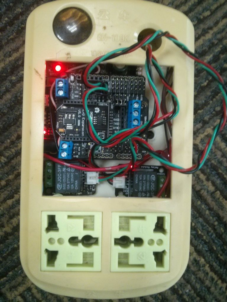
Step 2: Cleaning up, making room.
The outlet has a button, that will become useless now. I was considering the option of leaving the button on to bypass the relays in case I need the outlet for something else. But if that turns out to be a common case, I can just leave the Relays to always on, and turn off the Arduino.
Step 3: Internal power supply
The power supply for the Arduino can be grabbed out of any common USB charger. Make sure it is powerful enough for whatever you are going to use it. Since I’m always trying to reuse the whole thing, I’m guessing I’ll need quite a bit of power.
I went for this one at first, 300mA. Don’t make the same mistake. At first, I took it for granted that it was at the very least 500mA, but most likely 1A. Turned out it was not enough to even power the Relays. I found another one with 2A and switched it back. I forgot to grab a picture of the Power supply but is just a bit larger and a bit bigger. Had to cut some more plastic out of the outlet.
WARNING, be really careful, when plugging and wiring and powering it. If you are not extremely sure if the polarity of the wires, make sure you are not “nearby” when you plug it! If it breaks, and you have something else powered from the wall wart, everything will go dark. So take all necessary precautions!
Step 4: Layout Draft
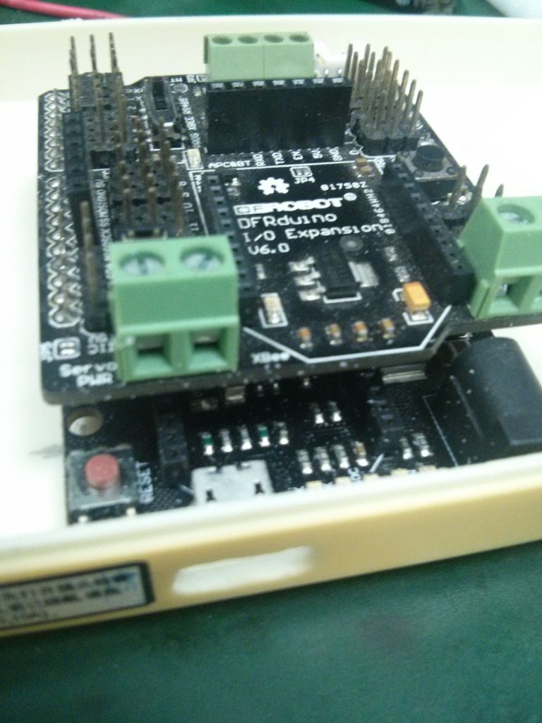
With the parts at hand and enough space, I started my first quick draft of the layout.
By the time I did the layout I had already cut the plugs. Would be better to put the Arduino on the right side, and the plugs with the High power all together. Separated and covered.
I’ve grabbed a bit of blue-tack sticky glue thing to hold the parts together. If you have gum and watched a lot of MacGyver then just go ahead. I’ve kept the high power wires from the relays outwards since I believe this is better, hope someone can correct me on this since I’m not entirely sure.
For more detail: Arduino Power outlet with exposed pins
- Why is this project better than cutting appliance wires?
Cutting wires makes hardware difficult to reuse, whereas this system allows testing without breaking the original appliance. - How do you ensure safety when working with high power voltage?
The design separates and covers high power voltage from the rest of the electronics inside a protective box. - What happens if the initial 300mA power supply is used?
A 300mA supply is not enough to power the relays, so a 2A supply was required instead. - Can the outlet button be kept for bypassing relays?
Yes, the button can remain to bypass relays, or relays can be set to always on while turning off the Arduino. - Where should the Arduino connector be positioned?
The connector should be placed next to the border of the outlet to allow programming access through a hole without opening the case. - Is it safe to modify the internal layout of the outlet?
You must be extremely careful with polarity and wiring; incorrect connections can cause everything powered by the wall wart to go dark. - What material can be used to hold parts together during layout?
Blue-tack sticky glue or gum can be used to temporarily hold parts together before final assembly.
