Welcome to my first instructable!
The project I want to share with you today is Arduino maze game, which became a pocket console as capable as Arduboy and similar Arduino based consoles. It can be flashed with my (or your) future games thanks to exposed ICSP header.
I had an idea few months ago to build a maze game on Arduino, but without hard-coded set of mazes. It should be able to generate a new maze for each level you are playing, so you never see the same maze again 🙂
Coding this was a bit of a challenge, since Arduino is limited in RAM memory, and then I found few examples how this can be done with simple Bo-Taoshi algorithm.
Code I used as a starting point i took by SANUKI UDON and his project HOW TO MAKE A MAZE GENERATOR USING ATTINY13A
Step 1: Breadboard Prototyping
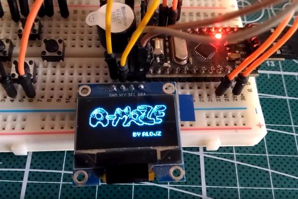
My starting point was with a small breadboard with only 4 buttons connected to move through maze, but later when i decided it should be a game console i added a few more buttons. On larger breadboard you can see 2 more buttons, and later i added a third one to be used as start/pause/menu button
Step 2: Parts Needed
- Arduino pro mini / Arduino Uno / Atmega328P chip
- 28 pin DIP socket (optional)
- SSD1306 OLED display
- Piezo speaker
- Push buttons – 7 pieces
- Coin cell battery holders
- Toggle switch
- Wires
- Prototype pcb (60x40mm)
Step 3: Breadboard Wiring / Schematic
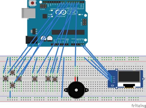
Connecting components as shown in diagram above.
Buttons:
- UP button: Arduino pin 7
- DOWN button: Arduino pin 6
- LEFT button: Arduino pin 9
- RIGHT button: Arduino pin 8
- A button: Arduino pin 5
- B button: Arduino pin 4
- START button: Arduino pin 2
SSD1306 OLED screen:
- SCL: Arduino pin A5
- SDA: Arduino pin A4
- VCC: Arduino VCC
- GND: Arduino GND
Buzzer:
- Buzzer positive: Arduino pin 3
- Buzzer ground: Arduino GND
Step 4: Source Code
A-Maze game source code can be found here: https://github.com/alojzjakob/A-Maze
Open in Arduino IDE and upload to your board or use ISP programmer to program your chip.
I recommend using USBTIny ISP, never had problems with it 🙂 but you can also use ordinary Arduino to program your chip.
In my case I did not use external crystal, so my Atmega328p chip works on internal oscillator which is 8MhZ.
For more info visit this link: https://www.arduino.cc/en/Tutorial/ArduinoToBreadboard.
Step 5: See It in Action
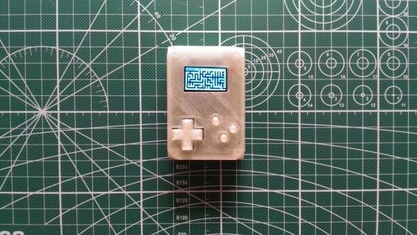
Step 6: Case and Miniaturisation
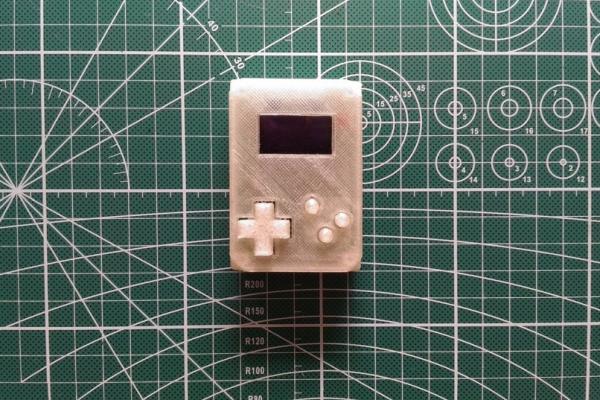
If you want to make this project permanent, with a nice looking case, here is the simple 3D printable case I designed: https://www.thingiverse.com/thing:2851100
In the pictures above you can see how all components are laid out on the 4×6 prototype PCB.
Most button wiring goes under the battery holders, try to make it as plain as possible, so battery holders can have relatively flush fit above the board with wires inbetween.
I also recommend do other wiring under the screen, since Atmega chip legs are soldered and exposed under the screen. When you are done soldering, put some insulation tape under the screen to prevent shorts etc.
ICSP header is optional, and if you decide not to expose it, it will make your assembly much easier, 6 connections less to take care of, but program the chip first before you solder it, or use 28 pin DIP socket so you can easily remove the chip for programming.
Source: Arduino Pocket Game Console + A-Maze – Maze Game