Summary of Arduino Orb Build Warden
This article details the construction of an Arduino-based "Build Warden," an ambient orb designed to provide visual alerts for broken source code autobuilds. The project repurposes electronics to replace commercial subscription-based devices, offering a customizable solution for monitoring system status. By utilizing an Arduino NG and standard lighting components, users can create a device that changes color to indicate build health, ensuring teams stay motivated to fix issues quickly.
Parts used in the Arduino Orb Build Warden:
- Multipurpose PC Board with 417 Holes
- Hookup wire (Solid, Red, Black, Green, 22 Gauge)
- Blue LEDs
- Green LEDs
- Red LEDs
- 220 ohm resistors
- Arduino NG
- Lighting Fixture
- Sharpie markers (Red, Blue, Green)
- Black Spray Paint
- Heat Shrink tube
- Solder
- Soldering Iron
- Round cut piece of 1/2 inch wood
- Standoffs Metal Hex
- Motherboard mounting screws
An Arduino based Ambient Orb designed explicitly for monitoring Source Code Autobuild systems. This orb can easy be repurposed for monitoring really anything that can have alerts from time to time.
Step 1: Purpose
Some time ago a co-worker passed me an article about “Extreme Feedback” devices that could be attached to your autobuild system with the express intent of making it very visible that the build is broken, and potentially being irritating enough to help motivate people towards fixing the broken build. Since reading this article I have been somewhat consumed with the concept of creating one of these devices for my team. Keeping builds clean is hard, and without a constant reminder, it can be very easy for people to let the build stay broken for long periods of time. This essentially defeats the purpose of doing autobuilds, and potentially even unit testing.
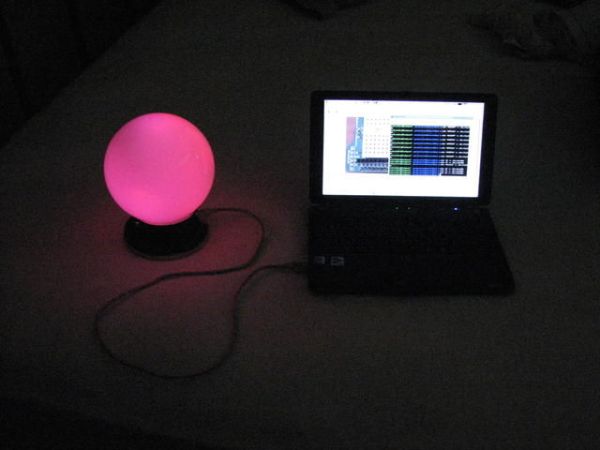
I Looked into the Ambient Orb, but I have to admit, I wasn’t particularly thrilled with the fact that it has a monthly subscription, and you can’t talk directly to it with your computer. So I started to teach myself electronics in the hope that I would be able to build one of these devices on my own. After a month or so, I ran into the Arduino platform, which struck me as the perfect platform for building an orb from scratch. This is the end result of my project is this, The Arduino Orb Build Warden.
Step 2: Parts
The design of the Build Warden was heavily influenced by Tod E. Kurt’s Arduino Ambient Orb from his Spooky Arduino class. I started with that as a base, and went from there. So first off, what parts do we need?
Radio Shack:
- Multipurpose PC Board with 417 Holes: (276-150) $1.99
- Hookup wire, Solid, Red, Black, Green, 22 Gauge, 90 ft, (278-1221) $5.99
Jameco:
- 3 x Blue LED, (183222) $2.95 ea
- 3 x Green LED, (334473) $1.45 ea
- 3 x Red LED, (33481) $0.27 ea
- 220 ohm, 1/8W resistors (100), (107941) $0.69
Sparkfun:
- Arduino NG, (Arduino-USB) $31.95
Home Depot:
- Lighting Fixture (Portfolio #74457 or similar), ~$10.00
Other Items:
- Red Sharpie (Optional)
- Blue Sharpie (Optional)
- Green Sharpie (Optional)
- Black Spray Paint (Optional)
- Heat Shrink tube (Optional)
- Solder
- Soldering Iron
- Round cut piece of 1/2 inch wood – cut to the size of the lighting fixture base)
- 2 x Standoffs Metal Hex (Sparkfun: COM-00126 if you don’t have any, which is unlikely)
- 2 x motherboard mounting screws (that fit the standoffs)
Alternatives:
I added this section, due to the fact that some items appear to no longer be available, here are some alternatives:
- 3 x Red LED, (Jameco #333526), $0.22 ea
- 2x 220 ohm, 1/8W resistors (5), (Radio Shack #271-011) $0.99 ea
-or-
- 500 assorted 1/8W resistors (Radio Shack #271-003) $12,99 (yes, it has 10 220 ohm ones)
Step 3: Get computer talking to the Arduino, Install software
I’m not going to take you through how to get Arduino working with your computer, and how to upload sketches to it. A full set of guides are available for getting the Arduino environment working with Linux, Windows or Mac OS X.
Once you have this environment set up and working, download the software I’ve written for the build warden. Follow the instructions from the above guides for installing the sketch on the Arduino.
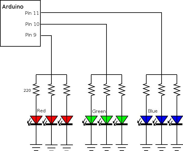
Step 4: Circuit Diagram
This project is really a very simple circuit. What we are going to be doing is running three wires from pins 9, 10 and 11. Each wire will branch to 3 220 ohm resistors, and then go on to 3 LEDs of the same color (9: Red, 10: Green, 11: Blue). These will all attach back to 1 wire that will go to ground.
Strictly speaking, each color should actually use different resistors, but the end result is in my opinion Good Enough. If you want to try and get the colors perfectly balanced, you have two options. Either correct it in the software, which is easy enough, or use different resistors for each color. In talking to Tod E. Kurt about this, his suggestion was this:
“For the color balancing you mentioned, the main thing you need to worry about is that because of the physics of LEDs, each color has a different voltage drop (Red is ~2.0V, Green is ~2.6V, Blue is ~3.3V), so really one should have different value resistors for each color. (i.e. if Red’s resistor is 220 ohm, Blue’s should be scaled down to about 130 ohm). I left this out of the notes because it can be confusing. You can deal with it in software by scaling the PWM values a corresponding amount. ”
You may want to put together a prototype board that has only 1 LED of each color. I did this to make working with the software easier. I included a photo of the prototype board here.
Lighting Fixture
3 x Blue LED
For more detail: Arduino Orb Build Warden
- What is the primary purpose of the Arduino Orb Build Warden?
The device is designed to monitor Source Code Autobuild systems by providing visible alerts when a build is broken. - Can this device be repurposed for other uses?
Yes, it can easily be repurposed for monitoring anything that generates occasional alerts. - Why did the author choose the Arduino platform over the original Ambient Orb?
The author avoided the monthly subscription fee and the inability to communicate directly with the computer found in the original product. - How should the LEDs be connected to the Arduino pins?
Three wires run from pins 9, 10, and 11, each branching to three resistors and then to three LEDs of the same color before connecting to ground. - Does pin 9 control the red or blue LED?
Pin 9 controls the Red LED, Pin 10 controls the Green LED, and Pin 11 controls the Blue LED. - What is the recommended approach for balancing LED colors?
Users can either use different resistor values for each color based on voltage drops or correct the balance in the software by scaling PWM values. - Is a prototype board necessary for this project?
No, but creating a prototype board with one LED of each color makes working with the software easier. - What are some alternative parts if specific items are unavailable?
Alternatives include different part numbers for Red LEDs and assorted resistor packs from Radio Shack. - Which software environment is required to upload sketches to the Arduino?
The Arduino environment must be set up and working on Linux, Windows, or Mac OS X. - What design heavily influenced the Build Warden?
The design was heavily influenced by Tod E. Kurt's Arduino Ambient Orb from his Spooky Arduino class.