Summary
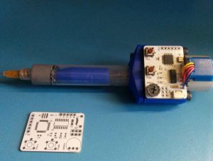
This is a motorized solder paste dispenser for soldering SMT boards that was inspired by this thing http://www.thingiverse.com/thing:384680. The home directory of this project is on github here https://github.com/zapta/misc/tree/master/paste_injector and it include hardware and firmware design of a compatible controller board that is Arduino compatible (it looks to the Arduino IDE as an Arduino Pro Mini).
Schematic: https://github.com/zapta/misc/raw/master/paste_injector/eagle/paste_injector_schematic.pdf
BOM: https://github.com/zapta/misc/blob/master/paste_injector/eagle/paste_injector_bom.csv
EEVBLOG discussion:
http://www.eevblog.com/forum/reviews/solder-pasteflux-manual-syringe-applicator/150/
I printed successfully using both PLA and ABS and standard slicing parameters (3 layer shells, 20% infill).
Hints, in assorted order:
- When printing the motor axis coupler, make sure to have your extruder temperature high enough for a good inter layer bonding.
- The step motor listed in the BOM is available on eBay from many sellers. They typically come with a ULN2003 driver PCB which is not needed here.
- When mounting the coupler on the motor, try to minimize the free play along the motor axis. I used a a sharp knife to pull out the motor axis while pushing the coupler toward the motor before tightening the coupler screws.
- You can insert the threaded inserts using any standard solder iron that fit into their holes. Preferably you will get tapered inserts similar to the ones specified in the BOM. If not, tapper them using a file or a Dremel tool. This is especially important for the insert that goes into the plunger rod. Otherwise, the internal hole hole will get clogged and the M4 threaded rod will not fit in.
- When inserting the threaded inserts, don’t push them too hard, let the heat do most of the work. This will result in better adhesion.
- I programed the controller board using an AVRISP MKII but you can use whatever works for you. Github has the binary image file that include the Arduino bootloader and a script that programs the AVR fuses.
- If you want to hack the firmware of the controller, solder a 6 pin header at the pads marked with FTDI and use an adapter such as FTDI Basic to hock the controller you your computer with the Arduino IDE. If you come with interesting firmware updates (e.g. having the red LED blinks proportionally to the speed), send me pull requests on github.
- Use thin and sticky solder paste. For example Chip Quik T5. If the solder paste doesn’t stick well to the PCB, dilute it as needed with IPA.
- Avoid air bubbles in the syringe. Air bubbles makes the rate flow control more difficult.
- The potentiometer controls the speed of the PRESS button only. I got the best results buy setting it on low and achieving a very slow rate of flow and then touching the PCB pads at a fixed rate to achieve consistent drops. This requires some practice.
- The potentiometer is linear but the firmware does logarithmic mapping to allow very fine control at low speeds.
Read more: Arduino Motorized SMT Solder Paste Dispenser

