1 Introduction
1.1 Overview
The Arduino microcontroller, a user-friendly yet robust single-board computer, has garnered significant popularity in both hobbyist and professional circles. Being open-source, Arduino boasts affordable hardware and freely available development software. This guide is tailored for students enrolled in ME 2011 or anyone encountering Arduino for the first time. Advanced users can explore various online resources.
Originating in Italy, the Arduino project aimed to produce cost-effective hardware for interaction design. Further details can be found on the Wikipedia page dedicated to Arduino, while the official Arduino homepage is located at http://www.arduino.cc/.
Arduino hardware comes in different variants, with Sparkfun (www.sparkfun.com) serving as a reputable source in the United States.
Focused primarily on the Arduino Uno board (Sparkfun DEV-09950, priced at $29.95), which is ideal for students and educators, this guide facilitates programming and the creation of interface circuits for reading switches, sensors, and controlling motors and lights with minimal effort. Many illustrations in this guide are sourced from Arduino’s documentation, the go-to resource for additional information. The Arduino section on the ME 2011 website, https://sites.google.com/a/umn.edu/me2011/, delves deeper into interfacing Arduino with the physical world.
Here is a visual representation of the Arduino board.
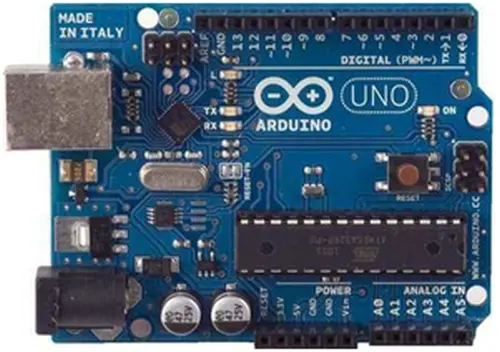
The Duemilanove board showcases an Atmel ATmega328 microcontroller functioning at 5 V, equipped with 2 Kb of RAM, 32 Kb of flash memory for program storage, and 1 Kb of EEPROM for parameter storage. Operating at a clock speed of 16 MHz, it can execute approximately 300,000 lines of C source code per second. Offering 14 digital I/O pins and 6 analog input pins, the board also includes a USB connector for communication with the host computer and a DC power jack for connecting an external power source ranging from 6 to 20 V, such as a 9 V battery, when running programs independently from the host computer. It provides headers for interfacing with the I/O pins using either 22 g solid wire or header connectors. For more detailed hardware specifications, refer to http://arduino.cc/en/Main/ArduinoBoardUno.
The Arduino programming language is a simplified variant of C/C++, making it familiar to those versed in C. However, even without prior knowledge of C, only a handful of commands are necessary to perform useful functions.
An essential feature of Arduino is its capability to develop a control program on the host PC, transfer it to the Arduino, and execute it automatically. Disconnecting the USB cable from the PC doesn’t halt the program’s execution, as it resumes from the beginning upon pressing the reset button. Moreover, even after disconnecting the battery and storing the Arduino for an extended period, the last programmed task resumes upon reconnection of the battery. This operational independence from the host PC allows for standalone functionality once the program is developed and debugged.
To set up a functional system, you’ll need:
1. Arduino Duemilanove board
2. USB programming cable (A to B)
3. 9V battery or an external power supply for standalone operation
4. Solderless breadboard for external circuits and 22 g solid wire for connections
5. Host PC running the Arduino development environment, with versions compatible with Windows, Mac, and Linux.
To install the necessary software, follow the instructions provided in the Getting Started section of the Arduino website (http://arduino.cc/en/Guide/HomePage). Completing the setup successfully is indicated by observing the pin 13 LED blinking, confirming that all software and drivers are correctly installed, and you can begin exploring with your custom programs.
For standalone operation, the board can be powered by a battery instead of the USB connection. While the external power source can vary between 6 and 24 V, a standard 9 V battery is commonly used for convenience. Instead of directly connecting the battery leads to the Vin and Gnd connections on the board, it’s recommended to solder the battery snap leads to a DC power plug and connect it to the power jack on the board for a more secure connection. A suitable plug option is part number 28760 from www.jameco.com. Here’s what the setup looks like.
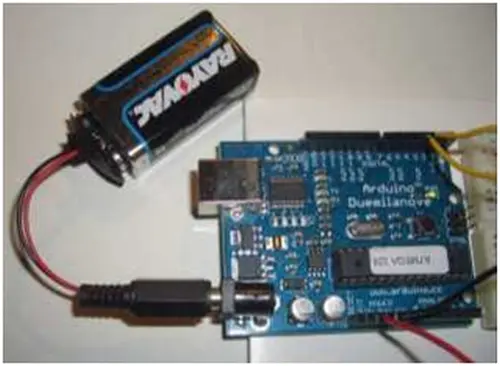
Unplug your Arduino from the computer. Attach a 9 V battery to the Arduino’s power jack using the battery snap adapter. Verify that the blinking program executes. This demonstrates the ability to power the Arduino via a battery and confirms that the downloaded program operates independently without requiring a connection to the host PC.
Moving forward, reconnect your Arduino to the computer using the USB cable. You can omit the battery for now. The green PWR LED will illuminate, indicating power. If a program was previously uploaded to the Arduino, it will commence execution.
Launch the Arduino development environment. In Arduino terminology, programs are referred to as “sketches,” although we’ll simply call them programs here.
Once the editing window appears, input the following program, ensuring attention to the placement of semicolons at the end of command lines.
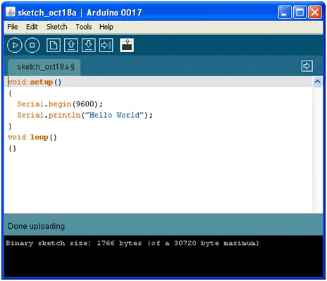
Press the Upload button or use Ctrl-U to compile your program and upload it to the Arduino board. Then, click on the Serial Monitor button. If everything proceeded smoothly, the monitor window will display your message, resembling something similar to this.
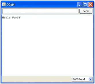
Press the reset button on the Arduino a few times and observe the results.
1.6 Troubleshooting
If a syntax error occurs in the program due to typing mistakes, an error message will appear at the bottom of the program window. Typically, examining the error message will reveal the issue. If problems persist, consider the following steps:
– Run the Arduino program again.
– Ensure that the USB cable is securely connected at both ends.
– Reboot your PC, as sometimes the serial port may become unresponsive.
– If you encounter a “Serial port… already in use” error during uploading:
– Seek assistance from a friend.
1.7 Solderless Breadboards
A solderless breadboard is an indispensable tool for quickly prototyping electronic circuits. Components and wires are inserted into the breadboard’s holes, with rows and columns of holes internally connected to facilitate easy connections. Wires extend from the breadboard to the Arduino board’s I/O pins. Use short lengths of 22 g solid wire with approximately 0.25″ insulation stripped at each end for making connections. Below is a photograph of a breadboard illustrating the internal connections. The pairs of horizontal runs at the top and bottom are convenient for supplying power and ground. Conventionally, the red-colored run denotes +5 V, while the blue-colored run represents Gnd. These power runs are sometimes referred to as “power busses.”
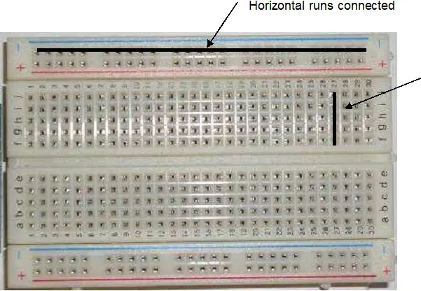
To ensure the Arduino board and breadboard remain connected, you can affix them to a piece of foam core, cardboard, or wood using double-stick foam tape or alternative methods.
2. Flashing an LED
LEDs (light emitting diodes) serve as practical tools for exploring the capabilities of Arduino. For this activity, gather an LED, a 330 ohm resistor, and short lengths of 22 or 24 gauge wire. The diagram to the right depicts the structure of an LED and its electronic schematic symbol.
Using 22 gauge solid wire, establish connections by linking the 5V power pin on the Arduino to the bottom red power bus on the breadboard and connecting the Gnd pin on the Arduino to the bottom blue power bus on the breadboard. Position the LED with its notched or flat side (located on the rim surrounding the LED base) facing the Gnd bus, and connect the opposite side to an available hole in the main area of the breadboard. Position the resistor so that one end aligns with the same column as the LED, while the other end occupies a vacant column. From this column, attach a wire to digital pin 2 on the Arduino board. Your setup will resemble the following illustration:
To verify the LED’s functionality, briefly detach the wire from pin 2 on the Arduino board and touch it to the 5V power bus. The LED should illuminate. If not, attempt to adjust the orientation of the LED. Once confirmed, reconnect the wire to pin 2.
In an LED, current flows from the anode (+) to the cathode (-), indicated by the notch. The schematic representation of the circuit you’ve assembled is depicted in the diagram to the right.
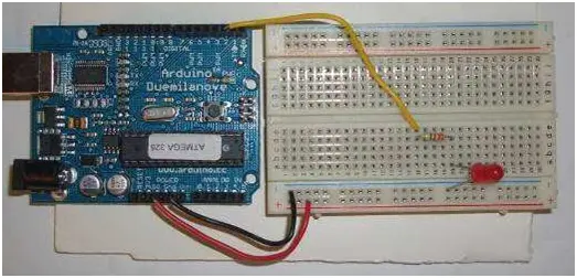
To verify the functionality of the LED, temporarily detach the wire connected to pin 2 on the Arduino board and touch it to the 5V power bus. The LED should illuminate. If it doesn’t, consider adjusting the orientation of the LED. Once tested, reconnect the wire to pin 2.
In an LED, current flows from the anode (+) to the cathode (-), which is indicated by the notch. The circuit you’ve assembled is illustrated in schematic form in the figure to the right.
Below is the Arduino program to create and execute:
“`cpp
void setup()
{
// Initialize pin 2 as an output
pinMode(2, OUTPUT);
// Set pin 2 to HIGH (turn on LED), wait for one second, then set it to LOW (turn off LED)
digitalWrite(2, HIGH);
delay(1000);
digitalWrite(2, LOW);
}
void loop()
{
// Empty loop as we’re not using continuous operations
}
“`
Did the LED illuminate for one second? Press the Arduino reset button to rerun the program. Now, attempt the following program, which flashes the LED at a frequency of 1.0 Hz. Any text after “//” on a line is considered a comment, as well as the text enclosed between “/*” and “*/” at the top. It’s beneficial to include comments in a program for clarity and documentation.
The pinMode command configures the LED pin as an output. The initial digitalWrite command instructs the Arduino to set pin 2 to HIGH, corresponding to +5 volts. This action allows current to flow from the pin, through the resistor, illuminating the LED, and finally reaching the ground. Subsequently, the delay(500) command pauses the execution for 500 milliseconds. The subsequent digitalWrite command then sets pin 2 to LOW, or 0 V, halting the current flow and thereby extinguishing the LED. The code enclosed within the loop() function’s braces repeats indefinitely, resulting in the LED blinking.
This exercise demonstrates how the Arduino can manipulate external devices. With suitable interface circuitry, the same code can control the activation and deactivation of motors, relays, solenoids, electromagnets, pneumatic valves, or any other devices operating on an on-off principle.
3. Reading a Switch
The LED demonstration illustrates how the Arduino can interact with the external environment. Many applications necessitate the ability to read the status of sensors, such as switches. The diagram on the right depicts a photograph of a pushbutton switch alongside its schematic symbol. It’s important to note that the symbol represents a switch with normally open contacts, which are closed when the button is pressed. If you possess a switch, utilize the continuity function of a digital multimeter (DMM) to discern when the leads are open and when they are connected as the button is depressed.
For this exercise, the Arduino will monitor the state of a normally open push button switch and present the findings on the PC using the serial.println() command. You’ll require a switch, a 10 kohm resistor, and several pieces of 22 gauge hookup wire. In the absence of a switch, you can substitute two wires and manually connect their free ends to mimic a switch closure. The diagram below showcases the schematic representation of the circuit on the left and a practical implementation on the right.
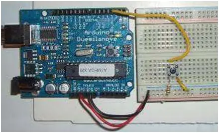
Here’s an Arduino program for you to create and execute:
“`cpp
void setup()
{
Serial.begin(9600);
}
void loop()
{
Serial.println(digitalRead(3));
delay(250);
}
“`
Open the Serial Monitor window. When the switch is open, you should observe a sequence of 1’s on the screen. Once the switch is closed, the 1’s will transition to 0’s. On the hardware side, when the switch is open, no current passes through the resistor. When there’s no current flow through a resistor, there’s no voltage drop across it, meaning the voltage remains the same on each side. In your setup, when the switch is open, pin 3 registers 5 volts, interpreted by the computer as a state of 1. Conversely, when the switch is closed, pin 3 connects directly to ground at 0 volts, yielding a state of 0 as detected by the computer.
Now, try the following program, illustrating how you can prompt the computer to wait for a sensor to change state:
“`cpp
void setup()
{
Serial.begin(9600);
}
void loop()
{
while (digitalRead(3) == HIGH)
;
Serial.println(“Somebody closed the switch!”);
while (digitalRead(3) == LOW)
;
Serial.println(“The switch is now open!”);
}
“`
Observe the activity in the Serial Monitor window as you press and release the switch.
4. Controlling a Small DC Motor
The Arduino can manage a small DC motor via a transistor switch. You’ll require a TIP120 transistor, a 1K resistor, a 9V battery with a battery snap, and a motor.
Below is an illustrative diagram detailing how to connect the components. These connections can be either soldered or established using a solderless breadboard.
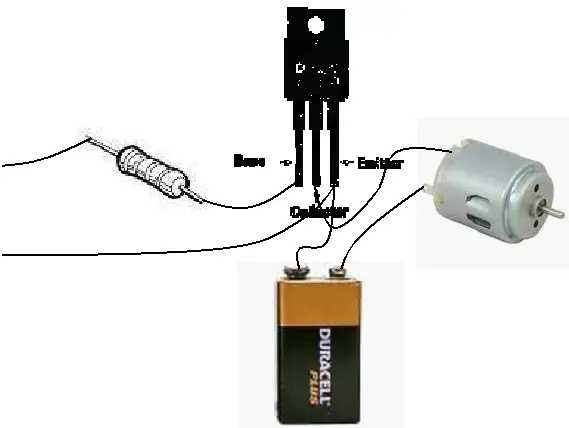
Pin 2 can function as any digital I/O pin on your Arduino board. Connect the negative terminal of the battery to the emitter (E pin) of the transistor, and also link the emitter of the transistor to the Gnd on the Arduino board.
To verify the functionality, use a jumper wire to bridge the collector and emitter pins of the transistor. The motor should activate. Then, detach the 1K resistor from pin 2 and connect it to +5V. The motor should activate again. Reconnect the resistor to pin 2 and execute the following test program:
“`cpp
void setup()
{
pinMode(2, OUTPUT);
digitalWrite(2, HIGH);
delay(1000);
digitalWrite(2, LOW);
}
void loop()
{
// Empty loop as we’re not using continuous operations
}
“`
The motor should operate for 1 second.
5. Arduino Hardware
The strength of Arduino lies not in its coding capabilities, but rather in its capacity to interface with the external environment via its input-output (I/O) pins. With 14 digital I/O pins labeled from 0 to 13, Arduino can control motors, lights, and detect the state of switches.
Each digital pin can either supply or draw about 40 mA of current, typically sufficient for most devices. However, more complex devices require interface circuits to manage them. For instance, running a motor directly from an Arduino pin is not feasible; instead, you need the pin to drive an interface circuit, which then operates the motor. A later section of this document illustrates how to interface with a small motor.
To interact with the external world, the program configures digital pins to either a high or low state using C code instructions, corresponding to +5 V or 0 V at the pin. These pins are connected to external interface electronics, which are further linked to the devices being controlled. The sequential process is depicted in the accompanying figure.
Follow this link for complete project: Arduino Microcontroller Guide: Getting Started with DIY Electronics
