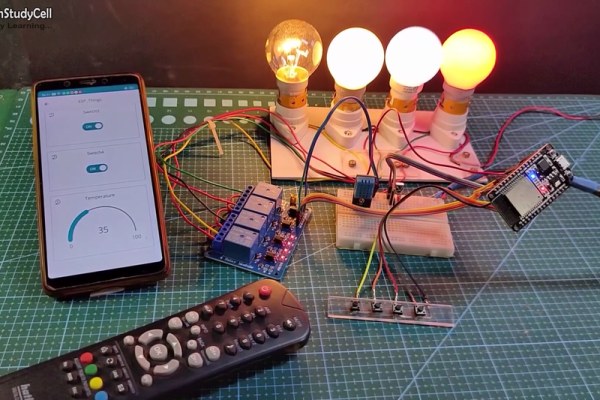
In this IoT project, I have shown how to make an IoT-based Home Automation with Arduino IoT Cloud & Alexa using ESP32 to control 4 home appliances with voice commands. If the internet is not available, then you can control the home appliances manually with switches and IR remote. During the article, I have shown all the steps to make this smart home system.
This IoT-based Home Automation system has the following features:
- Control appliances with Alexa and Arduino IoT Cloud Dashboard.
- Control the relays with the IR remote.
- Control appliances manually with switches.
- Control home appliances manually without internet.
- Monitor real-time feedbacks and room temperature in the Amazon Alexa app.
- All resources used for this project are FREE.
So, you can easily make this home automation project at home just by using an ESP32, DHT11 sensor, 1838 IR receiver, and relay module. Or you can also use a custom-designed PCB for this project.
Supplies
You can make this project just by using ESP32, DHT11 sensor, 1838 IR receiver, and 4-channel relay module. But if you use PCB then you need the following components.
- ESP32 DEVKIT V1
- DHT11 sensor
- 1838 IR receiver (with metallic case)
- Relays 5v (SPDT) (4 no)
- BC547 Transistors (4 no)
- PC817 Optocuplors (4 no)
- 510-ohm 0.25-watt Resistor (4 no) (R1 – R4)
- 1k 0.25-watt Resistors (6 no) (R5 – R10)
- 10k 0.25-watt Resistor (1 no) (R11)
- LED 5-mm (6 no)
- 1N4007 Diodes (4 no) (D1 – D4)
- Push Buttons (4 no)
- Terminal Connectors
- 5V DC supply
Step 1: Circuit Diagram of the ESP32 Home Automation Project
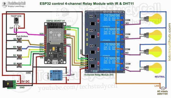
The circuit is very simple, I have used the GPIO pins D23, D22, D21 & D19 to control the 4 relays.
And the GPIO pins D13, D12, D14 & D27 connected with switches to control the 4 relays manually.
I have used the INPUT_PULLUP function in Arduino IDE instead of using the pull-up resistors.
IR remote receiver (TSOP1838) connected with D35. And the DHT11 sensor connected with RX2.
I have used a 5V mobile charger to supply the smart relay module.
Please take proper safety precautions while working with high voltage.
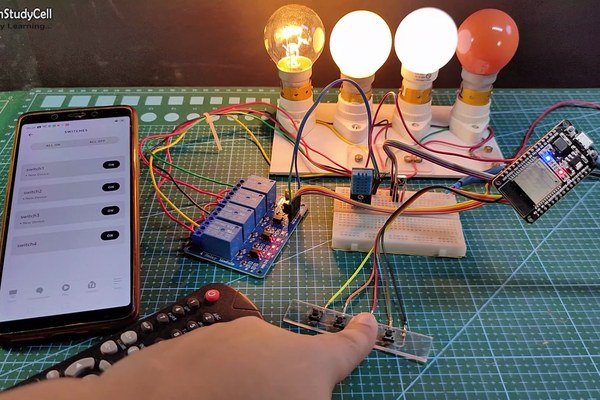
Step 2: Alexa Control Relay Using ESP32
You can control the home appliances from Amazon Alexa App and also monitor the room temperature if the ESP32 is connected with Wi-Fi.
You can also ask Alexa to turn on and off the appliances from anywhere in the world.
You don’t need any Echo DOT or other Alexa devices for this home automation project.
Step 3: ESP32 Control Relays With Arduino IoT Cloud Dashboard
You can also monitor the room temperature and control the home appliances from the Arduino IoT Cloud web dashboard and Arduino IoT Cloud Remote mobile app if the ESP32 is connected with WiFi.
In this project, I have used the FREE plan of Arduino IoT Cloud. In the FREE plan, you can control maximum of 5 relays or sensors.
When you control the relays from the Arduino IoT Cloud Remote mobile app the current state of the relay is also updated in the Amazon Alexa App.
Step 4: IR Remote Control Relays Using ESP32
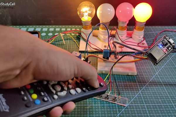
You can always control the relays from any IR remote.
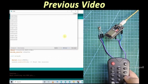
I will explain how to get the IR codes (HEX codes) from any remote in the following steps.
And if the ESP32 is connected with Wi-Fi, then you can also monitor the real-time feedback in the Amazon Alexa App & Arduino cloud dashboard.
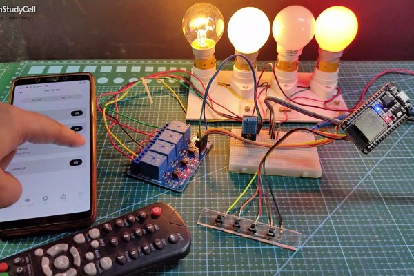
Step 5: Control Relays Manually From Push Buttons
If the WiFi is not available, you can control the relays from the pushbuttons.
When the WiFi is available, the ESP32 will automatically reconnect with the WiFi.
Please refer to the circuit diagram to connect the pushbuttons.
Step 6: Design the PCB for This Smart Home System
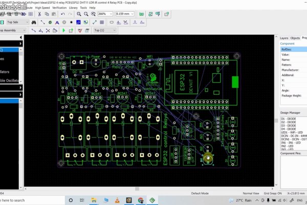
To make the circuit compact and give a professional look, I have designed the PCB after testing all the features of the smart relay module.
You can download the PCB Gerber file of this home automation project from the following link:
https://drive.google.com/uc?export=download&id=1ul0vrxWT95tU8UadmhOsaCp6fVvo_xi7
Step 7: Solder All the Components on PCB
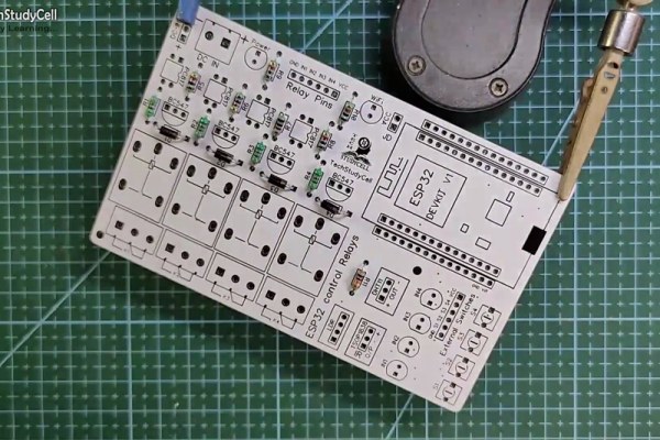
After that, I have soldered all the components as per the circuit diagram.
Then connect the ESP32, DHT11 sensor, and IR receiver with the PCB.
Step 8: Create Arduino IoT Cloud FREE Account
For this smart house project, I have used the Arduino Cloud Free plan.
Click on the following link to create an Arduino IoT Cloud account.
https://store.arduino.cc/digital/create
- Click on “GET STARTED FOR FREE“, then click on “create one“.
- Enter your birthday, then click on “Next“.
- Enter the email ID, user name, set password. Then click on “Sign Up“.
- Now click on “IoT Cloud“.
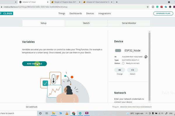
Step 9: Add ESP32 Device in the Arduino IoT Cloud
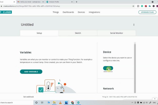
Click on the Select Device on the right.
- Select “Set up a third Party device“, then select device type as ESP32 and device model as DOIT ESP32 DEVKIT V1.
- You will get a Device ID and Secret Key which will be required in the code.
- Click on “Continue“, You will find the device added.
Step 10: Add Varriable in Arduino IoT Cloud
Now to control 4 relays, and get reading from the DHT11 sensor, you have to add 5 variables.
Click on the “ADD VARIABLE” button.
Enter name, then select Alexa compatible switch type. Variable Permission will be “Read & Write” and Variable Update Policy will be “On Change“.
In a similar way, you have to add the next 3 variables.
For the room temperature, reading select Alexa compatible Temperature Sensor. Variable Update Policy will be “Periodically“, and mention the interval time.
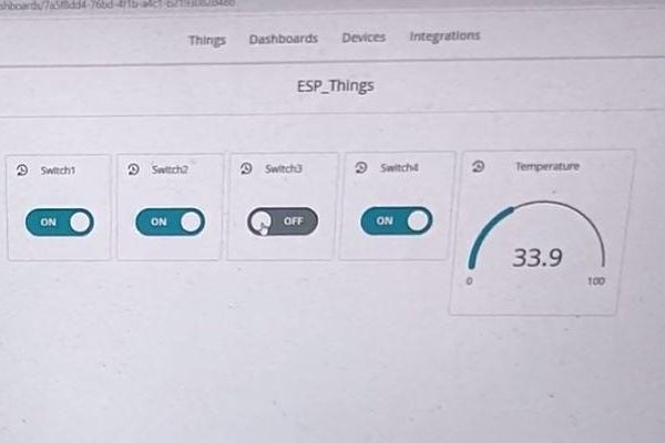
Step 11: Set Up Arduino IoT Cloud Dashboard
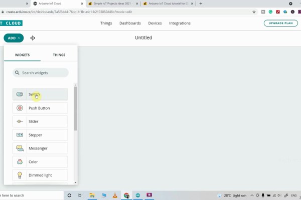
Now click on Dashboard on the top to set up the Arduino cloud dashboard.
Then click on Build Dashboard. After that click onthe EDIT icon.
Then click on ADD and select Switch.
Give a name to this Switch, then link a variable with this switch widget.
Then click on Done.
In a similar way, you have to add total 4 Switch widgets to control 4 relays.
For the temperature, select Gauge widgets and link the Temperature variable. You can also set the MIN and MAX limits.
Step 12: Get the IR Codes (HEX Code) From Remote
Connect the 4 home appliances with the relay module as per the circuit diagram.
Please take proper safety precautions while working with high voltage.
Connect 5-volt DC supply with the PCB. (I have used my old mobile charger 5V 2Amp) Turn on the 110V/230V supply and 5V DC supply.
Source: Arduino IoT Cloud ESP32 Alexa Voice Control Smart Home | IoT 2021