Summary of Build An Hygrometer Using Arduino
This article describes building a simple soil moisture monitor as part of an automated irrigation system. It uses a hygrometer sensor connected to an Arduino UNO to measure soil moisture levels, which are then indicated by three LEDs (red, green, and blue) corresponding to dry, moist, and wet soil ranges. The design includes wiring instructions for the sensor and LEDs with appropriate resistors. The Arduino sketch reads the sensor value, determines the moisture status, controls the LEDs accordingly, and outputs the data to the serial monitor for future integration with a controller.
Parts used in the Soil Moisture Monitor project:
- Hygrometer
- Arduino UNO
- Red LED
- Green LED
- Blue LED
- 220 ohm resistors (3)
- 10k ohm resistor
- Jumper wires
I am building an automated irrigation system for my vegetable patch. This will be a system that monitors the soil moisture level and then turns on a pump to send water to my garden according to the detected moisture level.
The water is coming from our rainwater tank, there is also an overflow on the tank that I’ve redirected to the garden (both the vegetable and ornamental gardens) so that water isn’t just sluiced off into my neighbors property. It’s been doing that since before we bought the property.
 This instructable is about one fairly simple part of the project, the soil moisture monitor.
For this instructable, you’ll need:
- 1 x Hygrometer (I bought mine from eBay)
- 1 x Arduino (I’m using a UNO)
- 3 x LED (Red, Green, Blue)
- 3 x 220 ohm
- 1 x 10k ohm resistor
- jumper wires
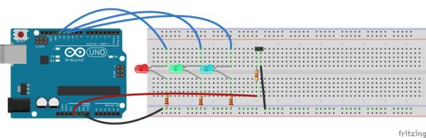
Step 1: Wire it up
There are three bits that are important in this project.
Connect the Hygrometer to Analog 0 (A0) on the Arduino, it doesn’t matter which side of the Hygrometer is connected to A0.
This connection also passes through the 10k Ohm resistor to 5V (we are splitting the load). It is the difference in load that the Arduino will detect on A0.
The other pin on the Hygrometer connects to GND on the Arduino.
If that’s as far as you go … you’d be done, of course you wouldn’t be able to see any Blinky lights … but that’s OK.
If you want to have a visual monitor of the moisture level, then you’ll be wanting some LED.
I’ve used pins 13 (RED), 12 (GREEN) and 11 (BLUE) in my sketch, you can use others if you want … I won’t oppress you.
Connect Pin 13 to the anode of the red LED (long leg)
Connect a 220 ohm resistor between the red LED cathode (short leg) and to GND
Connect Pin 12 to the anode of the green LED (long leg)
Connect a 220 ohm resistor between the green LED cathode (short leg) and to GND
Connect Pin 11 to the anode of the blue LED (long leg)
Connect a 220 ohm resistor between the blue LED cathode (short leg) and to GND
That’s it … you’re all wired up.
 Step 2: Arduino Sketch
The guts of the sketch simply reads the value on A0, works out if the value falls within a predefined range (0 – 400 = Dry, 400 – 700 = Moist and 700 + = Wet).
It also turns the appropriate LED on and off according to the same range.
Because I have grand plans of connecting the device to a controller at some later stage, I’m also sending the output to Serial.
The entire sketch is very simple … even I can understand it 🙂
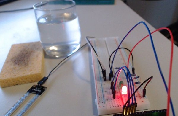
The video simply shows the monitor transitioning between states of Dry/Moist/Wet … with my ham fists in the action.
Oh, yeah … please excuse my colour blindness …
For more detail: Build An Hygrometer Using Arduino