This post is about an arduino-based intervalometer I built for my camera, a Fuji S9600 dSLR.
I decided to go for a very simple interface: a rotary switch in the middle of a plastic box which would allow me to select 12 pre-defined intervals. I went for a switch and not a potentiometer because I wanted to be certain about the option I select: the reassuring “click” of the rotary switch does exactly that!
Also, I wanted to make the device easy to use, so the labelling of the different options around the rotary switch was very important too.
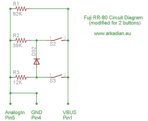
The Fuji S9600 (a.k.a. Fuji S9100 in the States) has a mini-B USB connector on the side which is used, amongst other things, for a remote shutter release cable. Bob Mahar has “dissected” an original Fuji RR-80 remote release cable and has revealed that the device is actually very simple inside; Bob’s great page on the Fuji RR-80 is here: http://www.trafficshaper.com/RR-80/RR-80.html.
Based on Bob’s page, I came up with the following diagram for the RR-80:
 The circuit of the RR80 is simple to build, but I couldn’t find a suitable mini-B USB plug: remember, the camera uses the 5th pin, which is not always available on the plugs you can buy online or at Maplin’s.
http://en.wikipedia.org/wiki/Universal_Serial_Bus
http://en.wikipedia.org/wiki/File:Types-usb_new.svg
After a couple of failed attempts to source a 5-pin USB mini-B connector, I ended up buying a cheap Chinese RR80 clone:
I was actually lucky, because this model has a 2.5″ jack on the side, which allows two cameras to be sync’d (not all the clones have this, I think the JJC clones marked “MA” have it). This meant that I could use a 2.5″ stereo connector in order to connect the arduino with the remote. All the arduino has to do in order to take a photo is to short 2 of the 3 parts of the stereo connector.
I was actually lucky, because this model has a 2.5″ jack on the side, which allows two cameras to be sync’d (not all the clones have this, I think the JJC clones marked “MA” have it). This meant that I could use a 2.5″ stereo connector in order to connect the arduino with the remote. All the arduino has to do in order to take a photo is to short 2 of the 3 parts of the stereo connector.
I used an old Sparkfun Skinny arduino (it is called “Arduino Pro” now and it’s not red anymore):
This is a 12-pole rotary switch from Maplin and 12 resistors:
I found a simple plastic box at Muji:
First things first: I converted the rotary switch into a “potentiometer”:
In case it’s not clear from the image above, I connected all the pins in the periphery with resistors. The yellow cable coming out from the middle pin of the switch goes to the analog In pin (pin 5 here). The black cable coming out from the 12th pin of the switch goes to the ground and the red cable coming out from the 1st pin of the switch goes to the 3.3V arduino output.
At the opposite side of the arduino board, I used a blue LED on pin 13 (and ground) and on pin 12 I connected a transistor, 2N222A: http://en.wikipedia.org/wiki/File:2n2222A_and_schema.jpg) and the cable (twisted red-black) from the 2.5″ connector.
Here is a better diagram of the wiring of the transistor (to keep things simple, only the transistor is shown here):
For more information on the use of transistors as switches: http://en.wikipedia.org/wiki/Bipolar_junction_transistor
After a few minor tweaks, the prototype was up and running:
The code loaded on the arduino is pretty simple really:
1 2 3 4 5 6 7 8 9 10 11 12 13 14 15 16 17 18 19 20 21 22 23 24 25 26 27 28 29 30 31 32 33 34 35 36 37 38 39 40 41 42 43 44 45 46 47 48 49 50 51 52 53 54 55 56 57 58 59 60 61 62 63 64 65 66 67 68 69 70 71 72 73 74 75 76 77 78 79 80 81 82 83 84 85 86 87 88 89 90 91 92 93 94 95 96 97 98 99 100 101 102 103 104 105 106 107 108 109 110 111 112 113 114 115 116 117 118 119 120 121 122 123 124 125 126 127 128 129 130 131 132 133 |
///////////////////////////////////////////////////
int swPin  =  5;  // 12-step switch
int ledPin = 13;  // Blue & pcb leds
int camPin = 12;  // Camera pin

int sw    = 0;  // 12-step resistance value
int stage = 1;  // 12-step stage (i.e. 1 - 12)

// this delay is specified by the rotary switch
int  delaySec;

// this is the current second count
long currentSec = 0;

// this is how long the shutter switch will be on
long shutterSec  = 100;

///////////////////////////////////////////////////
void setup() {

  // declare the swPin & ledPin as an OUTPUTs
  pinMode(ledPin, OUTPUT);
  pinMode(swPin,  OUTPUT);

// the serial is only used for debugging and for
// the calibration of the rotary switch
//  Serial.begin(9600);

}

///////////////////////////////////////////////////
// I
void loop() {
  readSwitch();
  timeCheck();

// printLine is only used for debugging and for
// the calibration of the rotary switch
//  printLine();
}

///////////////////////////////////////////////////
///////////////////////////////////////////////////
void timeCheck(){
  if(delaySec<=currentSec){

    digitalWrite(ledPin, HIGH);  // turn the ledPin on
    digitalWrite(camPin, HIGH);  // turn the camPin on

    delay(shutterSec); // keep the led and the switch on

    digitalWrite(ledPin, LOW);   // turn the ledPin off
    digitalWrite(camPin, LOW);   // turn the camPin off

    delay(1000-shutterSec);
    currentSec = 0;
  }

  else{
    delay(1000);
    currentSec = currentSec + 1;
  }
}
///////////////////////////////////////////////////
void readSwitch(){

  // read the value from the sensor
  sw = analogRead(swPin);

// the serial is only used for debugging and for
// the calibration of the rotary switch
//  Serial.print(sw);

  if(sw>=0  && sw< 20) {
    stage =  1;
    delaySec =   10;
  } // 10 secs
  if(sw>=20  && sw< 110) {
    stage =  2;
    delaySec =   20;
  } // 20 secs
  if(sw>=110  && sw< 200) {
    stage =  3;
    delaySec =   30;
  } // 30 secs
  if(sw>=200  && sw< 290) {
    stage =  4;
    delaySec =   60;
  } // 1 min
  if(sw>=290  && sw< 380) {
    stage =  5;
    delaySec =   90;
  } // 1.5 mins
  if(sw>=380  && sw< 480) {
    stage =  6;
    delaySec =  120;
  } // 2 mins
  if(sw>=480  && sw< 570) {
    stage =  7;
    delaySec =  180;
  } // 3 mins
  if(sw>=570  && sw< 660) {
    stage =  8;
    delaySec =  300;
  } // 5 mins
  if(sw>=660  && sw<750) {
    stage =  9;
    delaySec =  600;
  } // 10 mins
  if(sw>=750 && sw<850) {
    stage = 10;
    delaySec =  900;
  } // 15 mins
  if(sw>=850 && sw<950) {
    stage = 11;
    delaySec = 1200;
  } // 20 mins
  if(sw>=950 && sw<1024) {
    stage = 12;
    delaySec = 1800;
  } // 30 mins
}
///////////////////////////////////////////////////
void printLine(){
  Serial.print(" - Stage: ");
  Serial.print(stage);
  Serial.print(" (");
  Serial.print(delaySec);
  Serial.print(") - Next shot in: ");
  Serial.print(delaySec - currentSec);
  Serial.println();
}
///////////////////////////////////////////////////
|
 In order to calibrate the rotary switch, I had enabled the printLine() function (which is commented out in the loop() above and I got the following results on the terminal window (the first number on each line is the pin5 analog in reading):
Now it’s time to put everything in the box. I used my soldering iron to make the necessary holes on the box (I have a tip which I only use to make holes on plastic). Here is everything placed in the box for the first time (to make sure that everything fits the way it should).
The black surfaces you see on bottom of the box are foam boards; you can find them at art supplies shops. The foam boards are easy to cut and shape and, in this case, prevent the battery and the remote control moving around the box.
My next task was to come up with a way of indicating the time interval of each one of the 12 stages of the rotary switch. I didn’t think twice – this was a nice and easy job for processing. I created this image, which I got printed as a 5″ x 7″ in matt paper at photobox.com (10 s = 10 seconds, 1 m = 1 minute):
For more detail: Arduino Project: Intervalometer for Fuji cameras