In part 1 of our Arduino tutorial seres we covered the basics of how the Arduino works, and we’re going to use that knowledge in a hands-on project and see how this open-source hardware programming environment works when we’re actually trying to get something done with it.
After this, you’ll have more than enough information to be able to tackle your own projects with confidence – we’re going to build on the existing foundations to work on an entire project using nothing but cheap components and open source.
But before we tackle anything bigger, we need to fill in a few gaps left over from the first tutorial. In true TuxRadar fashion we’re going to make this a little more fun by re-creating a classic game from the 80s – Simon, a simple copying game. Players had to press buttons on Simon that corresponded to the musical notes that Simon played. You would first listen to the sequence of sounds before trying to re-create the pattern with the four large buttons on the game machine. The sequence would then get longer and harder to reproduce.
We’ve made a simplified version of this game using three LEDs (instead of notes) and three buttons. The idea of the game will be for the machine to play a sequence on the LEDs, and for the player to copy the sequence by pressing the corresponding buttons. Each time the player gets a sequence correct, we’ll extend the sequence by one, and the player’s score will be the length of the sequence they can remember.
Wiring the game
This is what you’ll need to build your own Simon:
- The Arduino board
- 3 x switches
- 3 x LEDs
- 3 x 1k Ohm resistors for the switches
- 3 x 1k Ohm resistors for the LEDs
We also use the solderless breadboard from the original article to position all the components and wire them together.
The first thing we need to do is plug in the switches. These have four prongs, but you only need to use two on the same side. We placed our three switches so they bridged the central divide of the breadboard, and we’ll only connect the two pins on one side of the divide, and use the space on the other side of the divide to connect the LEDs.
You need to give your design a little ergonomic consideration, because people are going to want to play with your device, but they won’t want to wrestle with the wires and resistors, which can get in the way. You also need to bear in mind the way that the LEDs are going to fit, as these need to line up with the buttons, so that it’s clear which LED in the sequence corresponds to which button.
We weren’t too successful with our layout, and if you share our lack of Jonathan Ive-style design skills, you may find that you need to start the whole process again when you understand more about the implications of where you put the wires and resistors.
The next job is to wire up the switches. We connect the 5V power output on the Arduino to one of the horizontal bus strips on the edge of the board. As you might expect for something called a ‘bus’, anything connected to one point within the horizontal line of points delivers a signal to every other point along the length of the board. They’re typically used to provide power and ground to the various components you connect to the central part of the breadboard (also known as the terminal strips), and this is exactly what we’re doing in this case.
From the horizontal line that now holds 5V of power, we need to connect a resistor to a leg of each switch. This is so we don’t give the switch too much power. If you don’t have a breadboard with any buses, you can still wire up our project, but you’ll need to make each connection back to the Arduino manually. We also need to connect a wire from the same leg that gets the power to three separate digital connectors on the Arduino, so that we can read the each button’s state. We used pins 5, 6 and 7.
You also need to connect the other leg of each switch to the ground connector on the Arduino (we used the one next to the 5V power input). The easiest way to accomplish this is to connect each leg to the bus next to the power, which in turn is connected to ground pin on the Arduino. That’s all there is to the switch wiring, and the LED wiring is very similar.
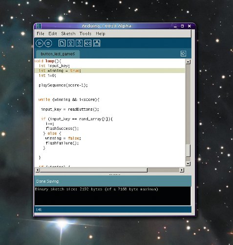
The Arduino IDE uses Java, so you can send your game directly to the device connected to a USB port.
Connecting the LEDs
On the other side of the divide, or notch, in the middle of the breadboard, we now need to place our three LEDs. These need to be close to each button, while leaving enough room to connect GND to one leg, and a control cable to the other. We used a bus on the other side of the notch to connect GND, and inserted the negative side of the LED directly into this (the shorter leg, or the flat side of the bulb). For the other leg, you need to connect a resistor, and to that a wire that goes back to one of the I/O pins on the Arduino. We used pins 10, 11 and 12.
Before we start the programming, here’s an overview of the connections we used on the Arduino:
- 1st switch Input 7, LED on 12.
- 2nd switch Input 6, LED on 11.
- 3rd Switch Input 5, LED on 10.
- 5V power to bus for the three switches.
- GND (Power) to alternative bus for three switches.
- other GND connected to bus used by the LEDs.
Now that we’ve got everything wired up, we need to switch to the programming environment to write the code required to play the game. We covered getting the environment working in the previous tutorial, and it’s fairly straightforward. The client uses Java, and if you run into problems running the client, you’ll probably have to remove the Braille terminal software, which conflicts with the software installed on the Arduino.
Programming
At the top of the new source file, we need to add the following to initialise all our connections and global values:
#define MAXSEQ 20
int rand_array[MAXSEQ];
int ledPin1 = 12;
int ledPin2 = 11;
int ledPin3 = 10;
int inPin1 = 7;
int inPin2 = 6;
int inPin3 = 5;
int score = 1;
The first define statement is used to declare the maximum size of the sequence of LEDs we’re going to flash, and this sequence is held in an array that’s created on the next line. An array is a string of elements, and each element in this example is going to tell the Arduino board which LED to light and which button that needs to be pressed – basically a number between 1 and 3.
Beneath these lines, we tell the Arduino which inputs the LEDs and switches are connected to (inPin and ledPin respectively). The final line creates a global value for score, which is a mark of how far the player has got through the sequence.
We now need to add the setup function that the Arduino uses to configure the various input and outputs:
void setup() {
  long val_rand = 0;
  pinMode(ledPin1, OUTPUT);
  pinMode(ledPin2, OUTPUT);
  pinMode(ledPin3, OUTPUT);
  pinMode(inPin1, INPUT);
  pinMode(inPin2, INPUT);
  pinMode(inPin3, INPUT);
  randomSeed(analogRead(0));
  for (int i=0; i<=MAXSEQ; i++){
    rand_array[i] = random (3);
  }
}
In this chunk of code we’re doing two things. Firstly, we’re telling the Arduino board which pins are used as output (to flash an LED), and which are being used as input (to read the state of a switch). We’re also using the setup function to fill the array with random values, and this is done in two steps.
The randomSeed function is reading input from pin 0. This isn’t connected, so it’s actually reading random noise that we’re using as a seed for the random number generator, and the generator is embedded within a ‘for’ loop that’s filling the array with a random value between 1 and 3.
Now we’ve got the configuration out of the way, we move on to the program logic. This is how it will flow:
- The sequence length starts at 1. We play the sequence so far on the LEDs.
- The player has to press each switch in turn that corresponds to each LED.
- Each time the player completes the sequence, the sequence is extended by one.
- When the player makes a mistake, they’re forced to restart the current sequence.
We’re going to implement this with just four functions. One function will read which button has been pressed (we’ll call it readButtons), another will play the sequence on the LEDs (playSequence), and we’ll need two further functions to signal success or failure (flashSuccess and flashFailure). Here’s the readButtons function:
int readButtons()
{
    int val1 = 0; int val2 = 0; int val3 = 0;
  do {

     val1 = digitalRead(inPin1); val2 = digitalRead(inPin2); val3 = digitalRead(inPin3);

  } while (val1 == HIGH && val2 == HIGH && val3 == HIGH);
    if (val1==LOW){
      return 0;
    } else if (val2==LOW) {
      return 1;
    } else if (val3==LOW) {
      return 2;
    }
}
All this is doing is waiting for the user to press a key, and then returning a value of 0, 1 or 2 depending on which key was pressed. We use these numbers because they correspond directly to the numbers we’re using to flash each LED. The important thing to note about switches is that they’re marked as HIGH when they’re not being presses, and LOW when they are. This is because they let the voltage through when open, and only lower the voltage when held down.
For more detail: Arduino hardware hacking: Part 2