Summary of Arduino Eye Strain Alarm
This article details the construction of an Arduino-based Eye Strain Alarm designed to remind users to take breaks from computer screens. The project involves 3D printing a custom case, soldering components like an RGB LED and buzzer to an Arduino Nano, and uploading customizable code. It serves as a physical alternative to phone alarms for reducing eye fatigue during prolonged screen use.
Parts used in the Arduino Eye Strain Alarm:
- 3D printed parts
- Arduino Nano without headers
- Passive buzzer
- SPDT slide switch
- Common Cathode RGB LED
- 2x 220 ohm resistors
- 2x M3x10mm screws with tapered head
- Felt
- 3-5 mm thick foam
- Thin stranded wire (24-26 gauge)
- Heat shrink tubing (1, 1.5, and 2 mm sizes)
With the COVID quarantine moving life online, I now spend many hours looking at my computer screen. Whether I’m doing school virtually, connecting with friends and family, or working on projects, all of these things keep me looking at my screen, as I am doing now. Because of this, sometimes my eyes start to hurt and my vision blurs from focusing on the screen for too long. I decided to make this device to remind me to look away from my screen at regular intervals during the day that would not be just another alarm on my phone. Hence, the Arduino Eye Strain Alarm was born.
Step 1: Materials
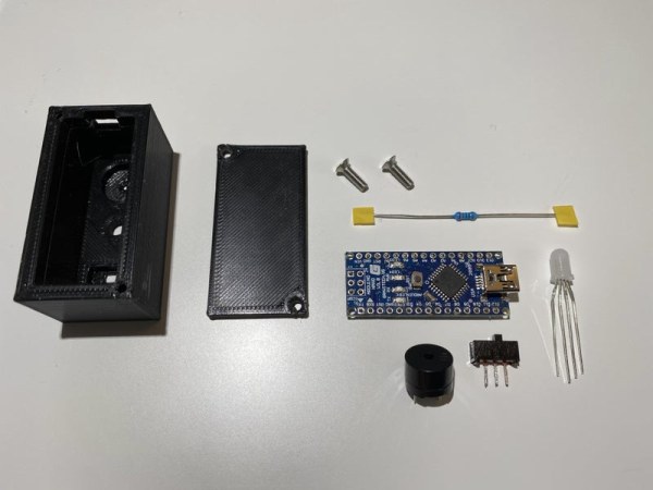
Components needed for this project:
- 3D printed parts
- Arduino Nano without headers
- Passive buzzer
- SPDT slide switch
- Common Cathode RGB LED
- 2x 220 ohm resistors
- 2x M3x10mm screws with tapered head
- Felt
- Some sort of foam about 3-5 mm thick
- Thin (24-26 gauge) stranded wire
- Various heat shrink tubing (I used 1, 1.5, and 2 mm sizes)
Tools to complete the task:
- 3D printer
- Soldering Iron
- Wire strippers
- Wire cutters
- Desoldering pump (If your Arduino has headers)
- Soldering helping hands(not necessary but very helpful)
- Scissors
Step 2: 3D Printing
I printed the parts with Hatchbox black PLA on my Creality Ender 5. I printed with 0.2 mm layer height and used tree supports for the USB hole.
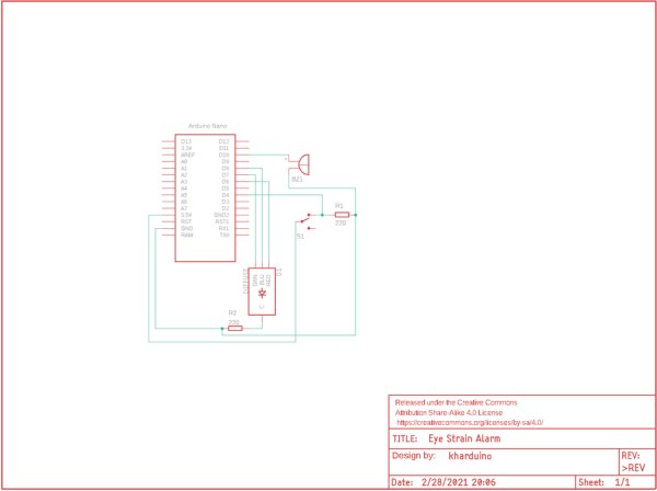
Step 3: Schematic
Step 4: Soldering Wires to the Components
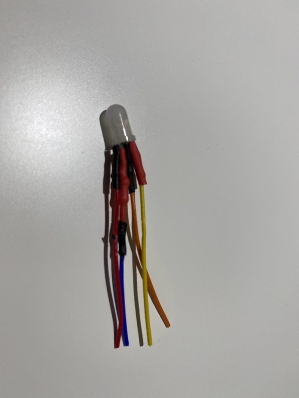
If your Arduino has headers, now would be the time to remove them. To start off with assembling the alarm, I cut wires to about 2.5 inches in length and soldered them to each of the leads of the LED, buzzer, and switch except for one of the outer leads of the switch because it is not needed. Don’t forget to also solder the resistor to the cathode of the LED and one of the pins of the switch like I did. Once you have soldered the connections, add heat shrink tubing so nothing gets shorted.
Step 5: Install Components
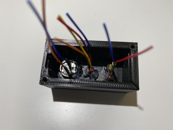
Once you have finished the last step, you can go ahead and use hot glue or superglue (I used a combination of both) to secure the three components in the box. For me, the LED had a tight fit so I did not really need to use any glue. Wait until the glue dries before going to the next step so nothing gets moved around when soldering.
Step 6: Finish Soldering
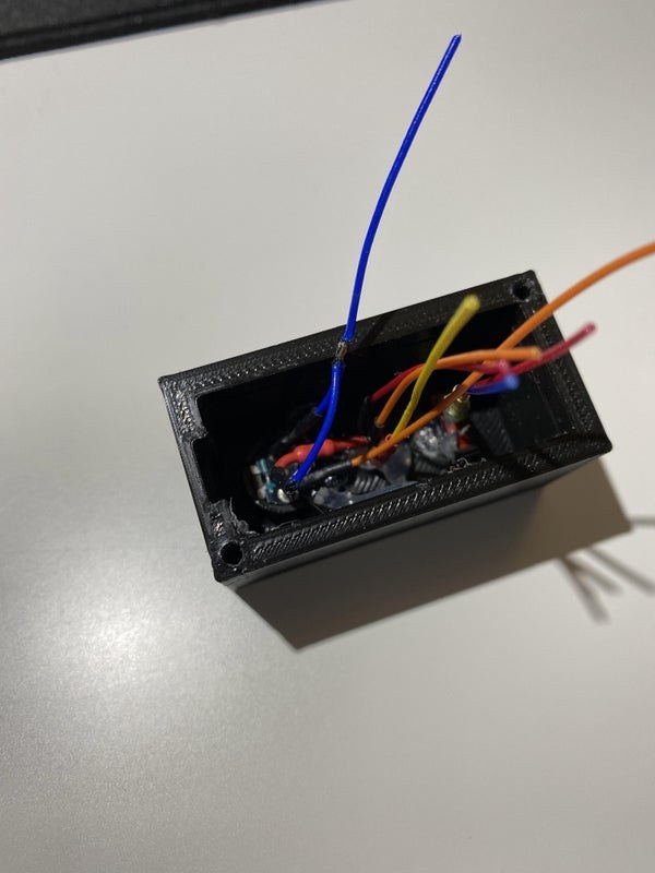
To finish the soldering, start by soldering all the ground leads together and soldering the ground to the Arduino. Once that is done, do the 5V wire then solder all of the data pins according to the schematic.
Arduino connections:
Switch pin without resistor -> 5V
All of the ground wires -> GND
LED red -> D6
LED green -> D7
LED blue -> D8
Switch data -> D4
Buzzer positive -> D10
Step 7: Upload Code
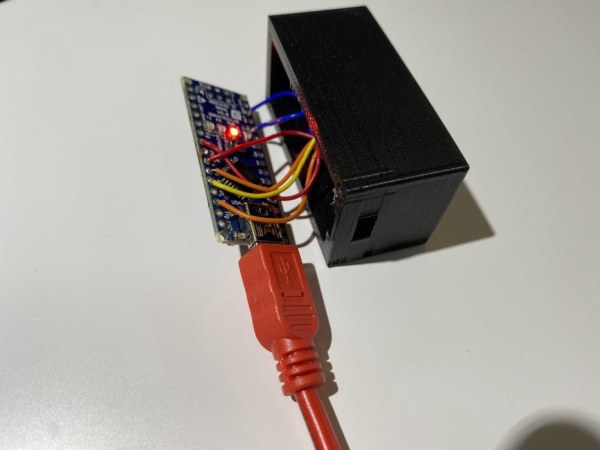
Now that all of the soldering is done, it is time to upload the code and make sure everything is soldered correctly. You can change the delay time as well as what the alarm sounds and looks like in the code to customize it to your liking. By default it is set to 15 minutes.
Step 8: Close the Box
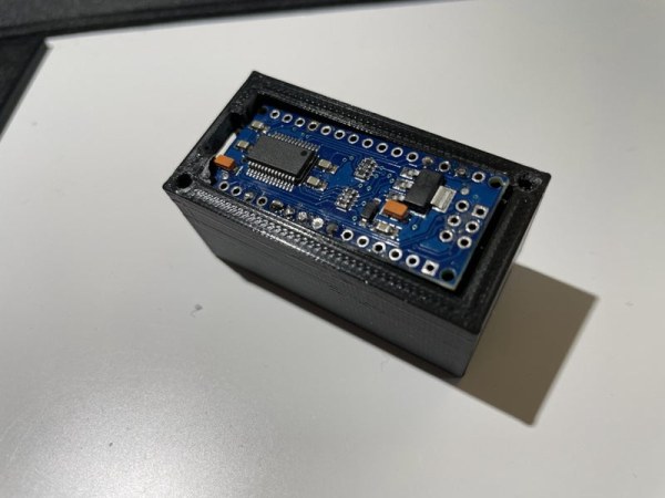
Now that you have checked that it works, push the Arduino into the case and place a piece of foam on it. I designed it this way so that later it could be disassembled and the parts used again. After everything is in place, screw the lid on using the two M3x10mm screws. For me the tolerances were kind of tight so I used a knife to widen the hole. Finally, glue a piece of felt on the bottom so it does not scratch the surface it is placed on.
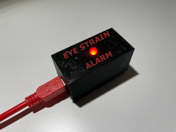
Step 9: Finish
Now you have your very own eye strain alarm that you can use to remind you to look away from your screen so your eyes don’t get strained. One improvement I already recognize would be to make the USB port have a more secure fit by reducing the thickness of the wall of the printed box. If you have any questions or suggestions, leave them in the comments and I will do my best to answer them.
Source: Arduino Eye Strain Alarm
- What is the primary purpose of this device?
The device is designed to remind users to look away from their computer screen at regular intervals to prevent eye strain. - Can I change the time interval for the alarm?
Yes, you can change the delay time in the uploaded code to customize it to your liking. - What default time is set in the code?
The code is set to 15 minutes by default. - How do I connect the LED red pin on the Arduino?
The LED red pin connects to digital pin D6 on the Arduino. - What materials are needed to print the case?
The author used Hatchbox black PLA printed with a 0.2 mm layer height and tree supports. - How do I secure the components inside the box?
You can use hot glue or superglue to secure the three components in the box. - Why is felt glued to the bottom of the device?
Felt is glued to the bottom so the device does not scratch the surface it is placed on. - What tool is suggested if the Arduino has headers?
A desoldering pump is suggested if your Arduino has headers that need to be removed. - Can the device be disassembled later?
Yes, the design allows for disassembly so the parts can be reused. - What improvement does the author suggest for the USB port?
The author suggests reducing the thickness of the wall of the printed box for a more secure fit.