
Using the Arduino development board (http://arduino.cc) has become a very popular way to create hardware prototypes that bridge the divide between the physical world and the Internet. This article outlines how to use an Arduino, some off-the-shelf electronic parts, the Processing programming language, and Google Documents to create a push-button reference desk transaction tally device.
The design: plugged into a computer at the reference desk, staff members push the appropriate button on the device when a reference transaction occurs, and the action is instantly tallied in a Google Document. Having a physical device on the desktop increases chances of proper collection of information since it is constantly visible and easily accessible, versus requiring staff members to click through a series of options in a piece of software running on the PC. The data can be tabulated in Google Documents or any other source that processes form-based HTML data.
 This article covers all of the major components of creating the project:
– Constructing the Arduino circuit and programming it
– Creating the Google Docs form
– Creating the Processing program that will listen for information from the Arduino and send it to the Google Docs form
by Tim Ribaric and Jonathan Younker
The Arduino microcontroller platform is popular with hobbyists for two main reasons: first, it is easy to use, requiring minimal knowledge of electronics and programming; second, it is very versatile in the way it can sense phenomenon from the physical world and translate it into signals that can be understood by computers. This basic understanding of the functioning of the Arduino provides the basis of a patron interaction tabulating device created by the Library Systems and Technologies department at Brock University.
Traditionally, tracking patron interactions at the various service points in a library was conducted with paper-based tally sheets. Each time a patron approaches the desk with an inquiry, a tick mark is placed in the appropriate category of the tally sheet. The data gathered can be used to keep track of how busy the desk is at specific points in time, to provide insights into what staffing levels are required, to get a general understanding of what the gaps in the service are by analyzing recurring questions, etc. Most often, this data is transcribed into an electronic database or spreadsheet where further analysis can be done. At some institutions – like Brock University – the paper tally form has been replaced with a software solution that allows service desk staff to enter this data electronically, using a piece of software or a web form to capture the interaction. The immediate downside to such a configuration is that it is often easy for staff to forget or to miss recording the interactions into the application when the service point becomes busy, the immediacy of paper and pencil is lost, and additional steps are introduced (opening the application, selecting the options, etc.)
This project aims to address the shortcomings of each of these collection styles (physical and electronic), by creating a hybrid approach facilitated by the use of an Arduino microcontroller.
A tabulation device (seen above) is placed on the service desk and connected to a computer with a USB cable. When a patron asks a question, the staff member simply taps a button, and the interaction is added directly to a Google Docs Spreadsheet (the data collection endpoint can easily be changed, if necessary). The immediate advantage of using this approach is that there is a lower chance of staff forgetting to tabulate the question, as the physical device would be difficult to overlook, the process is extremely quick and efficient, and the transaction is logged electronically so that it can be analyzed in a meaningful way. Three distinct pieces are involved in the synthesis of this machine (known as the Tabulatron): the construction and programming of the physical signaling device, a software component running on a computer to receive the signals from the physical device and to translate them to HTML POST calls, and a Google Docs Spreadsheet to collect the information.
The Signaling Device
The parts required to construct the device:
- An Arduino microcontroller board (Example)
- Four pushbutton switches (Example)
- One amber Light Emitting Diode (LED) (Example)
- One USB cable to interface the device to a computer and to provide power(Example)
- One enclosure to hold the constructed device (Example)
The example links are just suggestions and a wide variety of products could easily be substituted in their place. Local electronic stores are a great resource and can easily supply all the required components. The total cost to construct a Tabulatron is approximately $50.
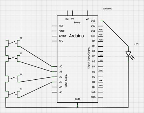
The Arduino microcontroller board comes in a variety of sizes and configurations designed to be used in various different environments (http://arduino.cc/en/Main/Products). The Arduino UNO board was used for this project, however, other Arduino boards could have been used instead. The only restriction is that the board chosen must have the required number of analog inputs to correspond to the number of desired buttons (smaller Arduino boards often have less input/output ports). The following diagram, created in an open source package called Fritzing (http://fritzing.org), shows a rendering of the completed circuit as a schematic.
The wiring can be described as follows:
- The LED is connected as an output on digital pin 13 and grounded to the Arduino
- One terminal of each of the 4 buttons is connected as input to analog pin 0, analog 1, etc.
- The opposite terminals of the push buttons are wired together in series and grounded to the Arduino
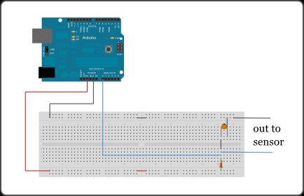
This exact circuit, rendered with physical wires and buttons, takes shape as the following:
Programming the Arduino Microcontroller
After the physical construction of the device is completed, it needs to be programmed via the Arduino integrated development environment (IDE). This IDE is an open source package and can be downloaded from the Arduino site (http://arduino.cc/en/main/software). Once programmed, the Arduino microcontroller will listen for button pushes and send a signal via the USB port to the connected computer. This connected computer is running a program that will be listening for these signals (outlined in the following section). For example, when the button connected to the Analog 0 input is pushed, a ‘0’ character is sent to the computer via the USB port and then the LED is told to flick on and off. This provides haptic feedback to the user that the button press has registered. When the button attached to Analog 1 input is pushed, a ‘1’ character is sent to the computer via the USB port followed by a blink of the LED, and so on. Programming the Arduino chip with the IDE only needs to be done once. Programs created with the IDE are called sketches, and the chip will retain this uploaded sketch indefinitely, even after power cycling.
The key function in this piece of code check_switches() was borrowed from the Adafruit site (http://www.adafruit.com/blog/2009/10/20/example-code-for-multi-button-checker-with-debouncing/). Adafruit is an online store for electronic components and also a resource hub for learning how to create with electronics. The following code is the complete program that the Arduino needs:
|
1
2
3
4
5
6
7
8
9
10
11
12
13
14
15
16
17
18
19
20
21
22
23
24
25
26
27
28
29
30
31
32
33
34
35
36
37
38
39
40
41
42
43
44
45
46
47
48
49
50
51
52
53
54
55
56
57
58
59
60
61
62
63
64
65
66
67
68
69
70
71
72
73
74
75
76
77
78
79
80
81
82
83
84
85
86
87
88
89
90
91
92
93
94
95
96
97
98
99
100
101
102
103
104
105
106
107
108
109
110
111
112
113
114
115
116
117
|
//Tabulatron Arduino Code//Will signal via Serial whenever a button is pressed//Circuit is pretty simple//-Pushbutton on A0//-Pushbutton on A1//-Pushbutton on A2//-Pushbutton on A3//-LED on 13 //Many,many thanks to Adafruit industries where I blatantly lifted this code//Buy something from there please//Global variables// Hash marked lines are not comments in the Arduino IDE as is common// with other languages, more details: http://arduino.cc/en/Reference/Define#define DEBOUNCE 10 byte buttons[]={14,15,16,17}; // the analog 0-5 pins are also known as 14-19 #define NUMBUTTONS sizeof(buttons)byte pressed[NUMBUTTONS], justpressed[NUMBUTTONS], justreleased[NUMBUTTONS]; int led = 13;voidsetup(){ byte i; Serial.begin(9600); pinMode(13,OUTPUT); //Make input & enable pull-up resistors on switch pins for(i=0;i<NUMBUTTONS;i++){ pinMode(buttons[i],INPUT); digitalWrite(buttons[i],HIGH); } start_led();}//LED blink sequence for when device starts up.voidstart_led() { digitalWrite(led,HIGH); delay(1000); digitalWrite(led,LOW); delay(1000);} //LED blink sequence for after a button is pressed //gives nice feeling that the machine is paying attention void flick_led(){ digitalWrite(led,HIGH); delay(250); digitalWrite(led,LOW); delay(250); digitalWrite(led,HIGH); delay(250); digitalWrite(led,LOW); delay(250); digitalWrite(led,HIGH); delay(250); digitalWrite(led,LOW); delay(250);}//This function does the heavy lifting of checking for button presses //and changing the values of the byte array to reflect button statesvoid check_switches(){ static byte previousstate[NUMBUTTONS]; static byte currentstate[NUMBUTTONS]; static long lasttime; byte index; if (millis() < lasttime) { //we wrapped around, lets just try again lasttime = millis(); } if ((lasttime+DEBOUNCE) > millis()){ //not enough time has passed to debounce return; } //ok we have waited DEBOUNCE milliseconds, lets reset the timer lasttime = millis(); for (index = 0; index < NUMBUTTONS;index++){ justpressed[index] = 0; //when we start, we clear out the "just" indicators justreleased[index] = 0; currentstate[index] = digitalRead(buttons[index]); //read the button if (currentstate[index] == previousstate[index]) { if ((pressed[index] == LOW) && (currentstate[index] == LOW)) { //just pressed justpressed[index]=1; } else if ((pressed[index] == HIGH) && (currentstate[index] == HIGH)) { //just released justreleased[index] = 1; } pressed[index] =! currentstate[index]; //remember, digital HIGH means NOT pressed } previousstate[index] = currentstate[index]; //keep a running tally of the buttons }}void loop() { check_switches(); for (byte i = 0; i < NUMBUTTONS; i++){ if (justpressed[i]) { Serial.print(i,DEC);//Print the button number to the serial port so that the processing app can listen for it. Serial.println(); Serial.flush(); //Always flush when you're done. flick_led();//An immediate couple of blinks of the LED makes the user feel like it has done something } } } |
The Arduino website has a clear and comprehensive tutorial on how programming the chip can be done. Reading through the tutorial before programming the Tabulatron will help clarify this process (http://arduino.cc/en/Guide/Windows | http://arduino.cc/en/Guide/MacOSX )
For more detail: Arduino-enabled Patron Interaction Counting