Summary of Arduino EMF Detector
This article outlines a DIY Arduino-based EMF Detector project for portable ghost hunting. The build involves assembling a circuit with resistors and LEDs on a breadboard or custom PCB, connecting a solid core wire as a probe, and uploading specific code to the Arduino. The author modified the pin connections from digital/analog ports to interface the components effectively with the microcontroller.
Parts used in the Arduino EMF Detector:
- 10- 330 ohm resistors
- 10- LED's
- 1-3.3m resistor
- 1-Solid core wire (probe)
- Breadboard
- Wires
- Battery & connector
- Arduino board
Here’s a small, quick project you can do with an arduino, the EMF Detector!
Step 1: Circut
- 10- 330 ohm resistors
- 10- LED’s
- 1-3.3m resistor
- 1-Solid core wire (this will serve as the probe)
- breadboard, wires, battery & connector for arduino to make it portable
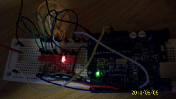
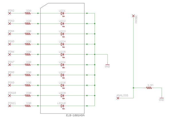
Step 2: Hooking up EMF
I can’t tell you much more at this point. I left the circut diagram so you can figure the rest out. I will be making a permanent PCB for this EMF detector. I will upload picture’s of the board layout in a few days when I get it done. Any questions leave them, I am usually quick to respond. Happy ghost hunting y’all!
Step 3: EMF detector code
This code is available at http://code.google.com/p/makezine/downloads/detail?name=EMF_detector_bargraph.zip&can=2&q=
I did not write this code so I do no want to take credit for it I just built the prototype to my liking.
Step 4: Custom PCB for EMF
Here is the finished custom pcb for the arduino EMF detector.
Step 5: Hooking up to arduino
I changed the code and went from digital pins 2-6-8-10-12- gnd the on the analog side pins 5 and gnd.
- 10- 330 ohm resistors
- 10- LED’s
- 1-3.3m resistor
For more detail: Arduino EMF Detector
- What is the primary function of the solid core wire?
The solid core wire serves as the probe for the detector. - How many 330 ohm resistors are required?
You need ten 330 ohm resistors for this project. - Where can I find the EMF detector code?
The code is available at the provided Google Code link for makezine downloads. - Which pins were changed for the analog side connection?
Pins 5 and gnd were used on the analog side. - Did the author write the code themselves?
No, the author did not write the code and built the prototype to their liking. - What type of resistor is listed alongside the 330 ohm ones?
A single 3.3m resistor is required for the setup. - Will the project be made into a permanent PCB?
Yes, the author plans to make a permanent PCB and upload pictures of the layout. - What is the intended use case mentioned for this device?
The device is designed for portable ghost hunting.