Summary of Arduino decision box (Attiny85)
This article details the construction of a wooden decision box powered by an Attiny85 microcontroller. The device features red, green, or orange LED indicators and a pushbutton to make random choices. Built within a 3x3x3 cm wood cube covered by an aluminum lid, the project emphasizes precise cutting, hollowing, and component mounting using tools like a Dremel and jeweler's saw.
Parts used in the Decision Box:
- Wood (3x3x3 cm)
- Red/green LED with common cathode
- Pushbutton
- Aluminum plate (3x3x~0.1 cm)
- 4 small wood screws
- Thermofusible glue
- Attiny85 chip
- 3V button cell battery
- Resistors (100, 500, and 10000Ω)
- 8-pin chip socket
- Tilt switch (optional)
- Thin non-solid core wires
So I was a bit bored this weekend (actually I wrote this some months ago) and since I had ordered a bunch of Attiny85 chips the week after I decided to make a quite random project with them.
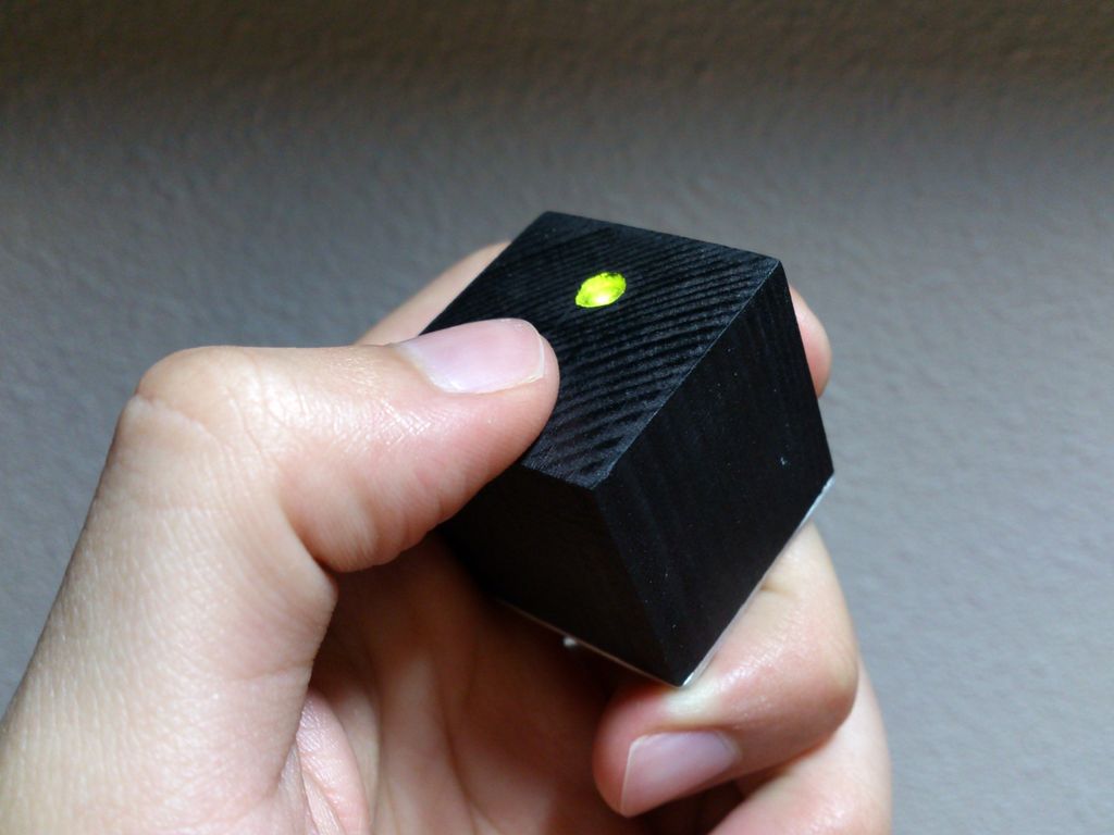
This is a decision box, it takes decisions for you by showing a green or a red light (it can also show orange if we programmed it to combine both colors). It’s made from wood and it has an aluminum plate to cover it all, I painted black because small wood objects tend to get quite dirty.
If you want to build one you’ll need the following materials:
- Wood (my final box is (3x3x3) cm)
- Red/green led with common cathode (negative leg at the middle)
- A pushbutton (you might want to get one long enough)
- Aluminum plate. (3x3x~0.1) cm
- 4x small wood screws.
- Thermofusible glue
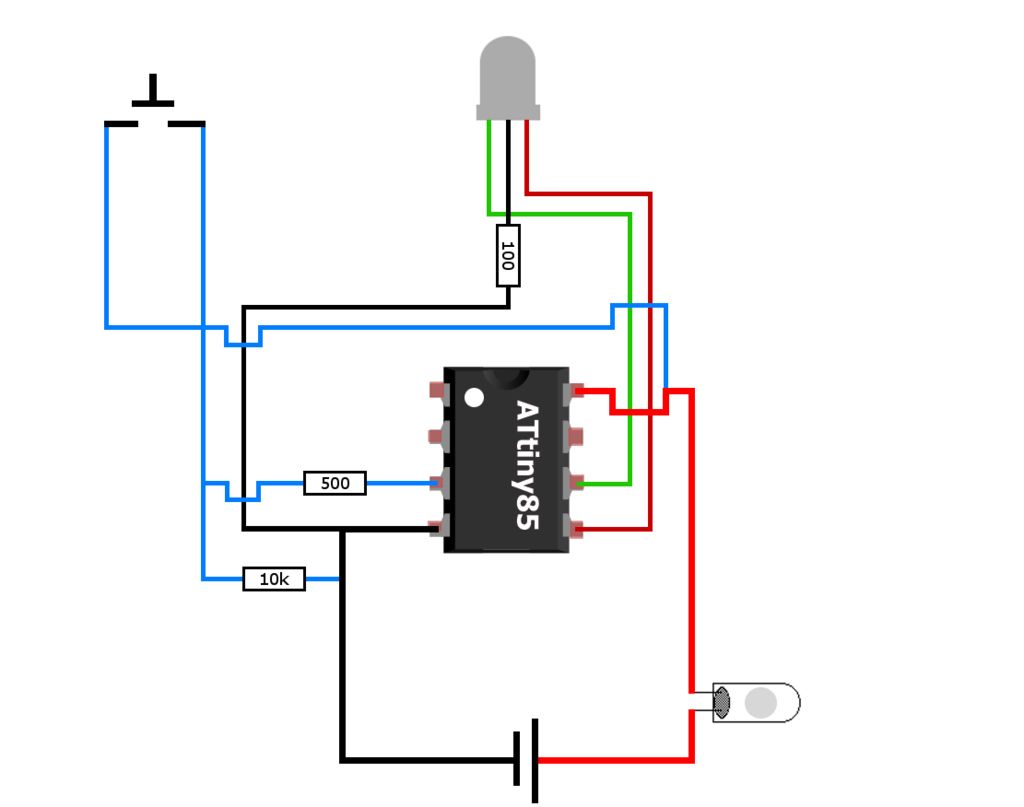
- Attiny85
- 3V button cell.
- 100, 500 and 10000Ω resistors.
- 8pin chip socket (if you plan to reuse the attiny)
- Tilt switch (optional but highly recommended)
- Thin wires (preferably non solid core)
These tools are also recommended:
- Dremel (performs better in this kind of tasks than a simple drill)
- A saw (jewelers saw) is needed if you plan to cut the wood cube and aluminum lid by yourself.
- Sandpaper (when it comes to making a perfect square there’s nothing like sandpaper)
Step 1: Making the body
Cut the wood cube, you can also use pre cut slats, this can save you a lot of time.
As always make the marks with the ruler and start to cut, unless you have very precise saws like a bandsaw or a circular wood saw the chances are you make the cube a bit irregular, this is were the painful method of measuring and sanding comes to play, mark the places you want to sand with a pencil and sand them placing the sandpaper over a flat surface.
If all goes well it should look like the picture.
Step 2: Hollowing it
Now you have make an empty space inside it, this operation is quite delicate and should be made with care.
What I did was to place the cube at my table clamp using a rag, so it doesn’t leaves marks on it, then with the Dremel I used a normal drill bit to make the initial holes, it’s very useful to put a bit of tape on the bit to avoid drilling through all the piece.
Once I have a bunch of small holes, I used the carving bit of the Dremel to carve a nice hole, finally with the sandpaper bit I smoothed the walls.
A 0,4 – 0,3 mm wall thickness is recommended.
IMPORTANT: leave more space on the corners where the screws will be placed, this grants you a bigger margin of error.
Step 3: Accomodate the components
Once you have a nice empty space where you can allocate your components you can make the holes for the push button and the LED , at this point you have two main options:
a) Drill the holes in the wood.
b) Drill the holes in the aluminum plate.
If I had the chance do this again I might make the holes at the aluminum plate because the pushbutton becomes easier to install since the thickness of the wood makes you have to use a long button, also when you unscrew it the whole thing comes out, if you do it the other way the components have to be stick to the wood and this might be quite annoying. The problem of attaching the components to the aluminum plate is the thermofusible glue doesn’t sticks to metals too well and it could end flimsy.
As always mark the right spot and have a firm hand.
Step 4: The lid
The aluminum plate is easy to cut off, just grab the box and with a pencil mark the outlines of the bottom of it, then with care, cut it out with a jeweler’s saw, you can later sand the corners and edges so they end smoother.
TIP: because the bottom of the box is probably going to be a bit irregular is useful to make a mark at the same corners of the box and plate so you can later align them correctly.
To make the holes get an appropriate bit and mark the points where you have to drill by making lines 3mm away from the sides of the plate.
TIP: to make sure the bit doesn’t moves and scrapes the metal you can punch a little hole with a pointy screw and a hammer, that will keep the bit in place, also clamp the plate tightly with a rag to prevent scratches, don’t drill it holding the plate with your hands, you could cut yourself if it get’s stuck, believe me, that happened to me once.
Step 5: Placing the lid
Once you have the holes in the plate you can drill the holes at the bottom of the box using it as a guide, now is when the markings you made to keep the pieces aligned are useful.
Use a Dremel or drill bit slightly thinner than the diameter of the screw.
You can sand the aluminum lid later as if you just wanted to sand one side, just make sure it’s tightly screwed and that you go to the direction where the wood part points and that you don’t pass over the same spot twice. Aluminum powder is very dirty and easily stains the wood.
For more detail: Arduino decision box (Attiny85)
- What is the primary function of this project?
The device takes decisions for you by showing a green or red light, and can show orange if programmed to combine both colors. - How should I cut the wood cube accurately?
You should mark places with a pencil and sand them on a flat surface to achieve a perfect square shape. - What wall thickness is recommended when hollowing the box?
A wall thickness of 0.4 to 0.3 mm is recommended for the hollowed interior. - Where is the best place to drill holes for the pushbutton and LED?
You can drill holes in either the wood or the aluminum plate; drilling in the metal makes installation easier but requires strong adhesive. - How can I prevent the drill bit from moving while drilling the aluminum plate?
Punch a little hole with a pointy screw and hammer to keep the bit in place before drilling. - Why should I avoid holding the aluminum plate with my hands during drilling?
Holding it with your hands could cause you to cut yourself if the bit gets stuck. - What safety precaution is needed when sanding the aluminum lid?
Ensure the lid is tightly screwed down and do not pass over the same spot twice to prevent aluminum powder from staining the wood. - Which tool performs better for cutting the wood and aluminum compared to a simple drill?
A Dremel performs better in these tasks than a simple drill.