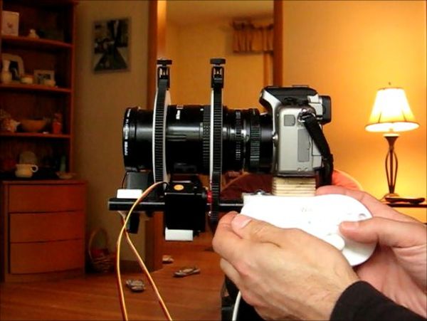
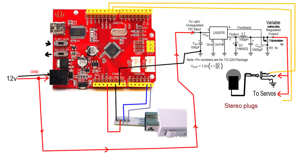
My Lumix GH2 Micro Four Thirds camera not only shoots fantastic high definition videos, but with inexpensive adapters I can use it with older manual lenses that are cheap and often very high quality. I shoot a lot of performance videos for my daughter’s dance studio, and I use an f3.5 Nikon 28-85mm zoom lens because it provides a good zoom range and a fast aperture for a zoom lens. The problem with this setup is that I have to zoom and focus the lens manually, and though I try to minimize zooming while shooting, there are times when it is essential for maintaining proper framing and for showing off the dancers’ skills. I’ve managed to learn to zoom manually without introducing excessive camera jitter (usually), but since I am also focusing manually, it’s a bit of a chore to quickly and smoothly adjust the focus after zooming in or out. To overcome this shortcoming I decided to build a power zoom and focus controller for my camera (which many others have done), with the critical goal of being able to automatically maintain the proper focus as the lens smoothly zooms in and out. After many months of prototyping I arrived at a great solution that uses an Arduino clone that accepts input from a Wii Classic controller, and which uses 2 hobby servos to move the lens. The total cost of the final product is less than $100.
The design that I eventually implemented has a number of advanced features:
– 2 joysticks provide continuously-variable speed lens control. Moving the right stick forward and back controls synchronized zoom and focus, and moving the left stick side to side controls just focus. The implementation of speed control also helps keep the servo noise down to acceptable levels.
– There are 6 programmable “goto” zoom/focus settings that can be programmed on the fly from the Wii Classic, and that will move the zoom and focus to the desired position just by pushing a button (left shoulder for widest zoom, right shoulder for most zoom, and a, b, x and y for any zoom/focus position).
– The maximum lens movement settings can also be programmed on the fly to ensure that the servos don’t try to rotate beyond the limits of the lens’s zoom and focus positions.
– D-pad provides single degree movements of zoom (up and down pad) and focus (left and right pad) to make precise adjustments for critical focus/zoom.
Here’s a demonstration of how the synchronized zoom – focus works on my GH2 with a Nikon 28 – 85mm zoom lens:
In this instructable I’ll cover the basics of how to build your own version of this controller, including the Arduino code and instructions for mounting the servos to a rail-based camera rig. I’ll mention how I built my rig, but since I’m not really happy with it, I won’t go into detailed steps on that and will leave it to you to figure out your own solution based on the pictures of my rig and some notes about how I made it.

This was my first attempt at building something with Arduino, though I’ve had some programming experience so it wasn’t too difficult for me to learn the basics of Arduino code. However, if you want to tackle this project and you haven’t already gained familiarity with setting up and programming an Arduino, I recommend that you go through the tutorials on the Arduino site, especially those for Servos. http://arduino.cc/en/Tutorial/HomePage
Step 1: Getting Started: Tools and Materials
You can complete the electronics for this project with just some wire strippers and a soldering iron. But to make the servo mounting arms it helps to have access to a bandsaw and a drill press (though careful work with a hand drill can negate the need for the latter). I also used a tablesaw to cut the sheet plastic and a table-mounted router with a 1/2 diameter core-box bit to cut the grooves in the plastic to match the rails on my home-made camera rail system.
Here is a list of the major supplies you’ll need to complete this project, but please go through the whole instructable before buying anything so that you’ll understand what to purchase in order to fit your own needs.
– Arduino or Arduino clone (I used a Seeeduino because it was a little cheaper than the Arduiino and provides the same functionality).
– Wii Classic Controller. I bought mine from eBay for around $10 shipped.
– Wiichuck Adapter (a little circuit board that plugs into your Wii Classic so you don’t have to cut the cable). I got this from FunGizmos for $4: http://store.fungizmos.com/items/212
– 2 standard sized hobby servos with nylon gears and ball bearings. The nylon gears are quieter and the ball bearings provide better support for the shaft when handling the load of stiffer zoom lenses. I bought some surplus servos from a local RC store for $5 each, but am replacing them with 360 degree digital servos that should be even quieter and more accurate, and those cost me $20 each from eBay.
– 2 lens gears to mount on your lens’s zoom and focus rings. I used the flexible ones that I found on eBay for $10 each, and made my own spacer rings to provide better resolution and a bit more mechanical advantage for the servos. You can also spend about twice as much and get lens gear rings that have built-in spacers, and these are also available on eBay. just search for “lens gear follow focus”.
– 2 Drive gears to mount on the servos to drive the lens gears. These need to be 32p or mod .8 gear pitch (which is the standard pitch for lens gears). I fashioned my own drive gears by fitting some $4 RC spur gears to the original servo control arms, but that required some work on a mini lathe that not everyone has. A better option would be to buy the servo-mountable gears from Servo City for just a few dollars more: http://www.servocity.com/html/32_pitch_hitec_servo_gears.html. While you’re ordering those, you’ll save yourself some trouble is you also buy a pair of male servo leads to make it easier to connect your servos to your Arduino and to swap servos if the need arises.
– 1/2 inch thick sheet plastic or 3/4″ thick aluminum to make the servo mounts. I used an old plastic cutting board, but if you do, make sure that it’s the harder ridgid kind (you should not be able to dent the surface at all with your thumbnail). The softer kind is UHMW and will not machine well enough for this purpose.
– knobs and matching carriage bolts for clamping the servo mounts to the rails.
Step 2: Choosing Gears and Servos for Your Lenses
Before you purchase your servos or gears, you need to understand some things about servos. Servos have a limited range of motion (typically 180), so if you want to be able to control your lens throughout its entire zoom and focus range, you need to do a little calculation based on your lens’s ring movement and the diameter of the lens gear that the servo will be driving. I think it’s best to just go through the process that I went through, so you can follow the same approach for your own system’s needs.
– Wii Classic Controller. I bought mine from eBay for around $10 shipped.
– Wiichuck Adapter (a little circuit board that plugs into your Wii Classic so you don’t have to cut the cable). I got this from FunGizmos for $4: http://store.fungizmos.com/items/212
– 2 standard sized hobby servos with nylon gears and ball bearings. The nylon gears are quieter and the ball bearings provide better support for the shaft when handling the load of stiffer zoom lenses. I bought some surplus servos from a local RC store for $5 each, but am replacing them with 360 degree digital servos that should be even quieter and more accurate, and those cost me $20 each from eBay.
– 2 lens gears to mount on your lens’s zoom and focus rings. I used the flexible ones that I found on eBay for $10 each, and made my own spacer rings to provide better resolution and a bit more mechanical advantage for the servos. You can also spend about twice as much and get lens gear rings that have built-in spacers, and these are also available on eBay. just search for “lens gear follow focus”.
– 2 Drive gears to mount on the servos to drive the lens gears. These need to be 32p or mod .8 gear pitch (which is the standard pitch for lens gears). I fashioned my own drive gears by fitting some $4 RC spur gears to the original servo control arms, but that required some work on a mini lathe that not everyone has. A better option would be to buy the servo-mountable gears from Servo City for just a few dollars more: http://www.servocity.com/html/32_pitch_hitec_servo_gears.html. While you’re ordering those, you’ll save yourself some trouble is you also buy a pair of male servo leads to make it easier to connect your servos to your Arduino and to swap servos if the need arises.
– 1/2 inch thick sheet plastic or 3/4″ thick aluminum to make the servo mounts. I used an old plastic cutting board, but if you do, make sure that it’s the harder ridgid kind (you should not be able to dent the surface at all with your thumbnail). The softer kind is UHMW and will not machine well enough for this purpose.
– knobs and matching carriage bolts for clamping the servo mounts to the rails.
For more detail: Arduino camera Lens Controller

