Summary of Arduino Bird Shoo!
Every spring, robins attack patio windows, creating messes. The author built an Arduino-based automated bird deterrent using a PIR sensor to detect movement and a stepper motor to wave a flag, successfully scaring birds away without ruining the view.
Parts used in the Bird Shoo Project:
- Arduino Uno
- Adafruit Motor Shield V2
- PIR sensor
- Stepper Motor 112090, 5 VDC
- Three color LED
- 1/8 steel rod, ~18" long
- 3 - 1 kOhm resistors
- Connector wires
- 3D Printed Enclosure
- Flashy ribbon for pom-poms
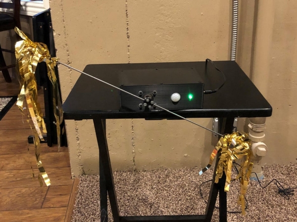
In the spring every year, we have a group of robins who start making nests around the house. We also have lots of windows in a patio area that when the robins see their reflection they think it’s a rival bird. They attack the windows repeatedly for months. They land on the chairs, railing and poop over everything. They also make a mess on the windows. We tried to cover the windows, place decals over them with some improvement, but now our windows have stuff covering them and ruins the view. So, I got to thinking, what if I take an Arduino, hook up a PIR sensor, add a motor connected to a flag of some sort. When a bird flies into the patio the PIR sensor will detect the bird and then the motor will wave a pomp-pomp and shoo that bird away. I rigged up a prototype in about an hour and IT WORKED!! It automatically scared the birds away, they built their nests in the trees, had babies but no more poop in the patio and chairs and the windows are not smudged! We had a few rains and the electronics got a bit of the weather, so this year I made an enclosure. Let the fun begin!
The Concept
The Arduino is hooked to a Passive Infrared (PIR) sensor. I set the PIR jumper to auto-reset (Some PIR’s do not have this jumper installed). I adjusted the PIR Pulse duration for just long enough for the Arduino to easily detect the pulse, but short enough so that the system can reset and shoo the next bird away. I used the AdaFruit Motor shield on the Arduino. I used a stepper motor (all stuff I had on hand). When the PIR detects movement, the Arduino drives the stepper in one direction and then the other. Once that sequence finished, I release the motor, I put a delay in the code and then reset the system to start looking for another detection. For grins I also added a three-color LED – I had a few on hand.
Supplies
- Arduino Uno
- Adafruit Motor Shield V2
- PIR sensor
- Stepper Motor 112090, 5 VDC
- three color LED
- 1/8 steel rod, ~18″ long
- 3 – 1 kOhm resistors
- Connector wires
- 3D Printed Enclosure
- Flashy ribbon for pom-poms
Step 1: The Circuit
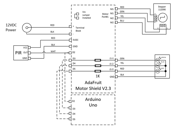
The Motor Shield stacks on top of the Arduino and shares I/O pins and power (that is the dotted lines).
I used a 12 VDC wall mount power supply. It was one I had on hand. The Adafruit Motor shield has an input of 6-12 VDC. Make sure it has enough current to drive the motor. There are lots of ways to power this. You could even use battery(s). Depends how many birds you have but you’ll have to do a but of recharging…..
I wired the jack to the Motor Shield terminal block (JP2). The motor Shield has a jumper that connects the power supply input down to the Arduino before the regulator. The Arduino regulated the 12 VDC to 5 VDC and is used for the logic. Above is a small schematic showing how this works.
I wired the PIR to the 5 VDC and GND pins on the motor shield header. I also connected the PIR output to pin 2 (D2). To drive the LED, I wanted to current limit the Arduino outputs using 1 K resistors. The Motor Shield has a prototyping board area for that. I could have soldered the resistors to the LED, but I thought this is cleaner. I wired D3, D4, D5 to these resistors and connected the other side to a soldered-in 3 pin header to the shield proto area (I called it J1). I wired J1 to the anodes (+) side of the LED. J1-1 is Green LED, J1-2 is the Blue LED and J1-3 is the red LED. (Ha – I ran out of blue wire so I used yellow wire). I connected the LED cathode common (-) to GND.
Next, I wired the stepper motor to Port 1. Make sure you check the coloring of your motor wires for the two windings, M1 and M2.
That’s it!
Step 2: PIR Sensor
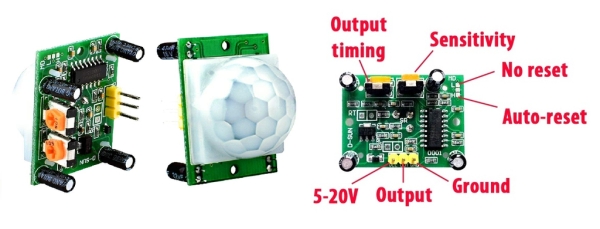
I use a simple PIR sensor (HC-SR501). This is a very cheap sensor that is widely used. Lots of on-line information on how to use this and how to use with an Arduino. The field of view is very wide. You can experiment with the sensitivity so that it works as you like. The output timing is how long the output pulse lasts. I kept it pretty short, long enough for my microcontroller and code loop to detect an event. Make the pulse longer than the entire animation sequence and the thing will run continuously.
Imagine this: Let’s say the entire motor animation loop code takes 10 seconds before it returns to the start and then resumes the loop looking for another PIR event. If your PIR pulse is 11 seconds or gets restarted because it’s too short, then the code will return to the start and sample the PIR, but the previous pulse is still active continually seeing a PIR event and will loop forever! How do you say? Remember the pom-poms are waving right in front of the PIR and will trigger another PIR event (and the too long pulse). Yikes!
Step 3: Code Walk-Through
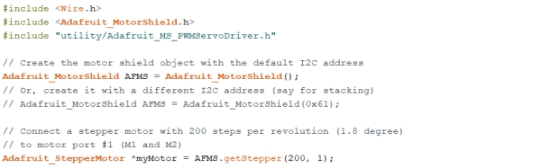
The Arduino code starts off loading the motor driver libraries. I won’t get into the details about that here. Please see the motor driver shield overview at Adafruit here:
https://learn.adafruit.com/adafruit-motor-shield-v2-for-arduino
You don’t need “#include “utility/Adafruit_MS_PWMServoDriver.h”. This is if you use PWM servo. I used a stepper motor for greater torque. If you have a beefy servo, at lease that library is called. (NOTE: for some reason my libraries for the PWM driver did not have “…_MS_..” in the filename. I changed the filename and it works)
I created the motor shield object with the default I2C address by adding: Adafruit_MotorShield AFMS = Adafruit_MotorShield(). I only had one shield so I used the default indexing leaving the “()” blank.
I used the Kysan 112090 stepper motor. These are very common and about $12. Whatever one you pick, look up the specs on it. For this motor the specs are:
- Four Wire: ED=M1; GRN=M1; YEL=M2; BLU=M2
- V = 4.2V
- I = 1.5A
- Step = 1.8 deg (step = 360/1.8 = 200 steps per revolution)
I connected my motor to port #1 (M1 and M2) and it has 200 steps so I put (200, 1) into the variables:
Adafruit_StepperMotor *myMotor = AFMS.getStepper(200, 1);
Step 4: Define Pins and Variables
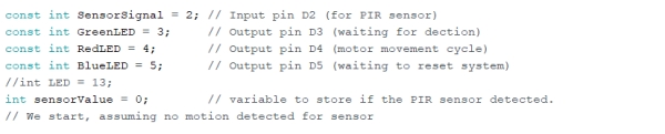
The next area is where I defined the pins and variables.
I defined the PIR input (D2), the three color LED output pins (D3, D4, D5). I gave them names: GreenLED, RedLED, BlueLED. I also pre-set the sensorValue to 0, assuming that there is no detection yet so animation doesn’t start once the loop begins.
Step 5: Void Setup()
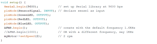
I set up the serial port for use in diagnostics. I now define the pins as inputs or outputs. I also use the default stepper frequency of 1.6kHz by leaving the variable blank “()” and a motor speed of 2 rpm. You can tweak this for your liking. I didn’t want to moving too fast or the torque would jerk the whole mechanism all over the place and the driver chip will get a bit hot.
Step 6: Loop() Function
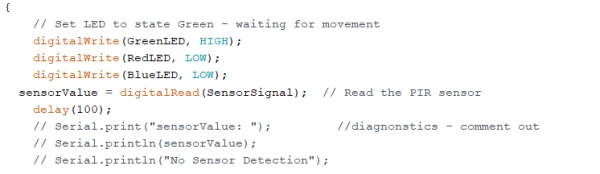
The first thing I do is set the green LED on (high) and all others off. I also read the PIR sensor and digitally read the PIR pin and place that values into the variable sensorValue. If the PIR is HIGH, there was movement and LOW if nothing detected. The last several lines I had in just for diagnostics so that I could read using the Arduino serial monitor. Got the whole thing working so I commented out. I like to keep the text in case I mess with the code and then I can use later.
Step 7: Continuing With the Code and the IF Loop:
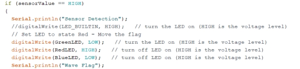
If sensorValue is HIGH (previously read PIR sensor = high, meaning that movement was detected), it drops into IF loop. I print “Sensor Detection” in the serial monitor (only if the computer is connected). I then set the LED to red and all other colors off.
Step 8: OK, I Like Das Blinkenlights:
Step 9: Continuing With the Code Within the IF Loop and Make the Motor Move:
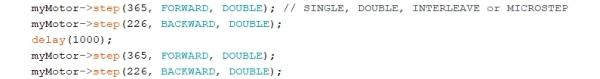
I first move the motor forward and backward. Wait a second and do it again. I arbitrarily selected the steps (365 and 226). No real reason for the numbers, I was goofing with different stepper modes and I ended up just leaving those in. See the Adafruit documentation on stepper motors and pick what you like. I picked Double, there are Single, Interleave and Microstep modes as well).
Step 10: Next Part of the Code:
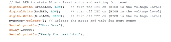
At this point the motor movement is done and time to reset everything. I now set the LED to blue and all other colors off. Why? Why not! It shows the unit is in the delay mode. I then release the motor. If I don’t release the motor, the stepper windings will continuously be driven holding at the position it left off with. No need to hold and drive all that current for no reason. I place about a 10 second delay in case the flag is a bit unbalanced and it rotates to a resting position. Pick whatever delay you want. That is the end of the IF loop and the code returns to the beginning of the loop which resets the LED and reads the PIR.
Step 11: Else Loop

If there is no PIR activity the IF loop drops to the Else loop. I make sure the LED is green and all others off.
And the whole thing starts all over.
Step 12: Enclosure
I have a 3D Printer. Best thing I ever got! I can make anything and make each part fit just what I want.
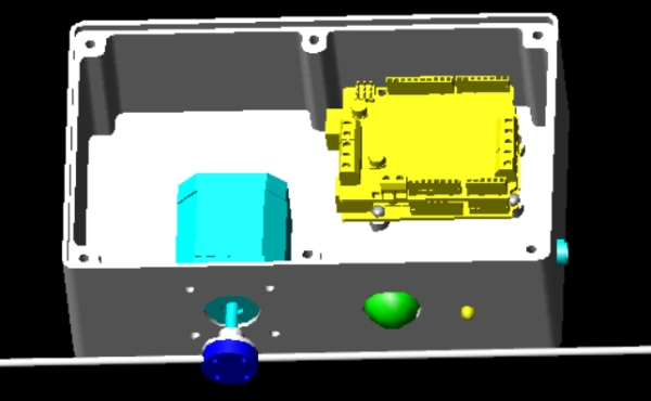
To keep the elements from frying my electronics I made an enclosure for the whole thing. Internal to the enclosure, I made some mounting tabs for the Arduino/Motor Shield stack. I like to use metal inserts so I can use screws. I could have made the standoffs with a small hole and force a screw into it, but you need to pre-drill so you don’t break them off or split them. There are lots of sites how to do this. Once you do it enough it gets easy.
https://www.makerbot.com/professional/post-process…
Step 13: Enclosure Mounting
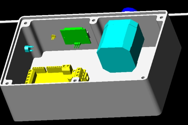
I also installed the PIR sensor, motor and LED. I might come up with a rubber gasket to cover the motor hole, and punch a small hole that the shaft will go through. Don’t have any on hand so I’ll work that later. I also installed a power jack. This way I can use a wall mounted power supply and connected power though the jack.
I also made a small stand off for the PIR so that only the circular bezel protrudes. I used really small screws for this one so I used a small hand drill to pre-tap the holes. No inserts for this one!
Source: Arduino Bird Shoo!
- How does the system detect birds?
The system uses a Passive Infrared (PIR) sensor connected to pin 2 to detect movement when a bird flies into the patio. - What motor is used to scare the birds?
A Kysan 112090 stepper motor is used with an Adafruit Motor Shield to wave the flag back and forth. - Can I use a battery instead of a wall power supply?
Yes, you could use batteries depending on how many birds you have, but you would need to recharge them periodically. - Why did the author add a three-color LED?
The LED indicates status: green for standby, red for detection, and blue during the delay/reset phase. - What happens if the PIR pulse duration is too long?
If the pulse lasts longer than the animation sequence, the system will loop forever because it continuously sees an active event. - How is the electronics protected from rain?
The author created a 3D printed enclosure with mounting tabs and metal inserts to protect the electronics from weather. - What voltage does the Motor Shield require?
The Adafruit Motor Shield accepts an input of 6-12 VDC from a wall mount power supply. - How many steps per revolution does the stepper motor have?
The motor has 200 steps per revolution based on its 1.8-degree step angle.