It is a well known fact that Stepper motors are awesome! The only downside is that they can be a bit trickier to get going than servos and plain old DC motors. If you are interested in the inner mechanics and theory of stepper motors, check this excellent post on PCB heaven. If you happen to have one of the cheap little 28BYJ-48 steppers with 5 wires and a little driver board with them, check this tutorial instead. Here, I will focus on how to get a bipolar stepper motor (typically 4 wires) working with Arduino and a H-Bridge IC like the L293D , or the drop in improved replacement – SN754410NE .
Arduino Bipolar Stepper Motor
Step 1: Confirm the wiring of your motor
If you have some documentation about your motor than you are set. All we need here is to see how the 4 wires coming out of your bipolar stepper motor are paired in the internal wingdings.
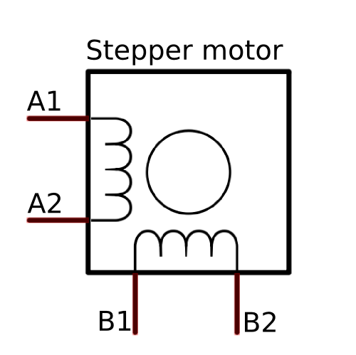
If you got your motor from a mystery eBay special, or from an old printer, then you need to do some testing with a multimeter. Once you figure out how your stepper is wired, remember the colours of the 4 wires, or mark them.
Even if your stepping motor has 6 wires, you can still control it like a four wire stepper motor, you just need to identify the center tap wires. You can do that following the same tutorial on stepper motor wiring mentioned above. Once you figure out the two center taps, you can simply mark them and ignore them, as you will leave them disconnected, focusing on the remaining 4 wires instead.
Step 2: Prototype the circuit
Bipolar stepper motors require a bit more complex electronic control circuit than unipolar steppers, like the 28BYJ-48. You need to be able to reverse the current in the two coils A1A2 and B1B2, much like reversing the current across a DC motor to get it to spin forward and backwards. The easiest way to do that is with an H-Bridge IC, like the L293D ( datasheet ), or the SN754410NE ( datasheet ). You will also need a prototype board, some hook-up wires, an Arduino Uno, or compatible mocrocontroller, a computer with the Arduino IDE loaded and of course, a stepper motor.
If you are going to follow along the examples below, you can connect the H-Bridge to your Arduino as follows:
H-Bridge Input 1 -> Arduino Digital Pin 2
H-Bridge Input 2 -> Arduino Digital Pin 4
H-Bridge Input 3 -> Arduino Digital Pin 6
H-Bridge Input 4-> Arduino Digital Pin 7
Both Enable pins on the H-Bridge are connected to 5v (always enabled). Note that stepper motors can draw significantly more current than the Arduino 5volt reail can source, so you should get a separate power supply for your motor, and remember to connect all grounds.
Step 3: Arduino Code
There are two Arduino libraries that help to manage stepper motors and I will cover both in the examples below, but first I like to test out my set up with some basic Arduino code. This will not be an efficient way to drive the motor, but is a good way to get started and get a feel of what it takes to spin the stepper motor.
Example 1: Basic Arduino code (no library)
There are two Arduino libraries that help to manage stepper motors and I will cover both in the examples below, but first I like to test out my set up with some basic Arduino code. This will not be an efficient way to drive the motor, but is a good way to get started and get a feel of what it takes to spin the stepper motor. The code below should make your stepper move counterclockwise 48 steps and then counterclockwise for 48 steps. It just happens that after some trial and error I figured that my old mystery stepper has 48 steps per rotation.
int inA1 = 2; // input 1 of the stepper
int inA2 = 4; // input 2 of the stepper
int inB1 = 6; // input 3 of the stepper
int inB2 = 7; // input 4 of the stepper
int stepDelay = 25; // Delay between steps in milliseconds
void setup() {
  pinMode(inA1, OUTPUT);
  pinMode(inA2, OUTPUT);
  pinMode(inB1, OUTPUT);
  pinMode(inB2, OUTPUT);
}
void step1() {
  digitalWrite(inA1, LOW);
  digitalWrite(inA2, HIGH);
  digitalWrite(inB1, HIGH);
  digitalWrite(inB2, LOW);
  delay(stepDelay);
}
void step2() {
  digitalWrite(inA1, LOW);
  digitalWrite(inA2, HIGH);
  digitalWrite(inB1, LOW);
  digitalWrite(inB2, HIGH);
  delay(stepDelay);
}
void step3() {
  digitalWrite(inA1, HIGH);
  digitalWrite(inA2, LOW);
  digitalWrite(inB1, LOW);
  digitalWrite(inB2, HIGH);
  delay(stepDelay);
}
void step4() {
  digitalWrite(inA1, HIGH);
  digitalWrite(inA2, LOW);
  digitalWrite(inB1, HIGH);
  digitalWrite(inB2, LOW);
  delay(stepDelay);
}
void stopMotor() {
  digitalWrite(inA1, LOW);
  digitalWrite(inA2, LOW);
  digitalWrite(inB1, LOW);
  digitalWrite(inB2, LOW);
}
// the loop routine runs over and over again forever:
void loop() {
  for (int i=0; i<=11; i++){
    step1();
    step2();
    step3();
    step4();
  }
  stopMotor();
  delay(2000);

  for (int i=0; i<=11; i++){
    step3();
    step2();
    step1();
    step4();
  }
  stopMotor();
  delay(2000);
}
There are many ways to improve the code above, for example you can make it non-blocking by eliminating the delay function, or create a function for cockwise / counter-clockwise rotation etc. This is what is good about starting with no pre-defined libraries: you are in full control and can experiment and learn in the process.
Example 2: Arduino Stepper library
The Arduino IDE comes with a pre-installed Stepper library that does a decent job controlling a stepper motor for basic applications. The example below uses the stepper_OneStepAtATime example sketch (File->Examples->Stepper->stepper_OneStepAtATime) to move my stepper one full rotation clockwise, one step at a time, while pausing between steps and printing the step number to the console.
/*
 Stepper Motor Control - one step at a time

 This program drives a unipolar or bipolar stepper motor.
 The motor is attached to digital pins 8 - 11 of the Arduino.

 The motor will step one step at a time, very slowly.  You can use this to
 test that you've got the four wires of your stepper wired to the correct
 pins. If wired correctly, all steps should be in the same direction.

 Use this also to count the number of steps per revolution of your motor,
 if you don't know it.  Then plug that number into the oneRevolution
 example to see if you got it right.

 Created 30 Nov. 2009
 by Tom Igoe

 */

#include <Stepper.h>

const int stepsPerRevolution = 48;  // change this to fit the number of steps per revolution
                                     // for your motor

// initialize the stepper library on pins 8 through 11:
Stepper myStepper(stepsPerRevolution, 2,4,6,7);

int stepCount = 0;         // number of steps the motor has taken

void setup() {
  // initialize the serial port:
  Serial.begin(9600);
}

void loop() {
  if (stepCount < stepsPerRevolution) {
    // step one step:
    myStepper.step(1);
    Serial.print("steps:" );
    Serial.println(stepCount);
    stepCount++;
    delay(500);
  }
}
Example 3: AccelStepper library
Once you have covered the basics and are ready to try and push your stepper motor to the limit, you can look into the AccelStepper library. This library provides additional features and optimized, non-blocking code for controlling multiple steppers at the same time. This library does not come pre-installed with the Arduino IDE, so you need to download the zip file and install it (Sketch -> Import Library… and select the zip file downloaded from the link above.). The example below uses the library to gradually accelerate my stepper motor over 12,000 steps, then decelerate it back and repeat the process in the opposite direction.
#include <AccelStepper.h>

#define HALF4WIRE 8

// Motor pin definitions
#define motorPin1  2     // A1
#define motorPin2  4     // A2
#define motorPin3  6     // B1
#define motorPin4  7     // B2

// Initialize with pin sequence IN1-IN3-IN2-IN4 for using the AccelStepper with 28BYJ-48
//AccelStepper stepper; // Defaults to AccelStepper::FULL4WIRE (4 pins) on 2, 3, 4, 5

AccelStepper stepper1 (HALF4WIRE, motorPin1, motorPin2, motorPin3, motorPin4, true);

void setup() {
  stepper1.setMaxSpeed(1200.0);
  stepper1.setAcceleration(100.0);
  stepper1.setSpeed(100);
  stepper1.moveTo(12000); //250 full rotations @ 48 steps each = 12,000 steps

}//--(end setup )---

void loop() {

  //Change direction when the stepper reaches the target position
  if (stepper1.distanceToGo() == 0) {
    stepper1.moveTo(-stepper1.currentPosition());
    delay(500);
  }
  stepper1.run();