
Summary of MCP41100 an Arduino Controlled Potentiometer
Summary: This guide shows how to control an MCP41100 digital potentiometer with an Arduino via SPI to replace analog pots. It covers required materials, MCP41100 characteristics and resistance calculation, Arduino example code to sweep the wiper across 256 taps, and simple applications like LED dimming and DC motor speed control using the pot with a 555 PWM circuit.
Parts used in the MCP41100 Arduino Controlled Potentiometer:
- Arduino Board
- Digital Potentiometer MCP41100
- Resistor 100 Ohm
- LED
- Breadboard
- Jumper Wires
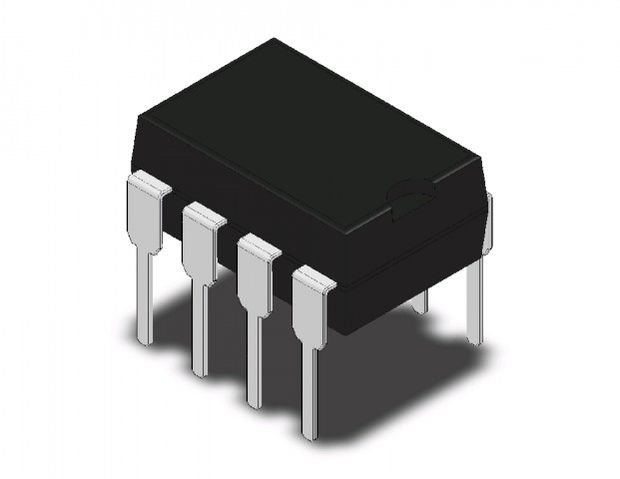
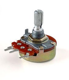
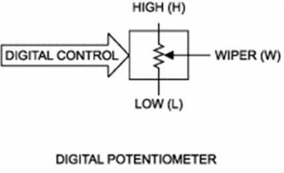
We know the analog potentiometer , is a three-terminal resistor with a sliding contact that forms an adjustable voltage divider .
MCP41100 an Arduino Controlled Potentiometer:
1)volume controls on audio equipment.
2) Control the amplifier Gain and offset .
3) Transducer ” displacement transducers “.
and many Other application , But did you you want to control the resistance value by Microcontroller instead of using analog one ?
Analog potentiometers have some problem with MCU , Microcontroller doesn’t have an easy way to interface with them .
The Digital Potentiometer , give you an ability to adjust the resistance ,allowing you to control a voltage splitter with digital signals
In this simple instructable I will show you how to control Digital Potentiometer MCP41100 Using Arduino IDE .
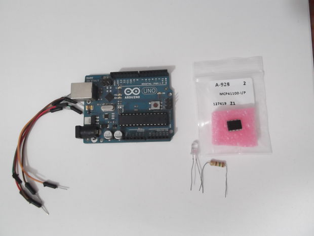
we will need :
1) Arduino Board .
2)Digital Potentiometer MCP41100 .
3)Resistor 100 Ohm
4)LED
5)BreadBoard.
6JumperS
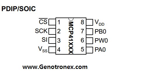
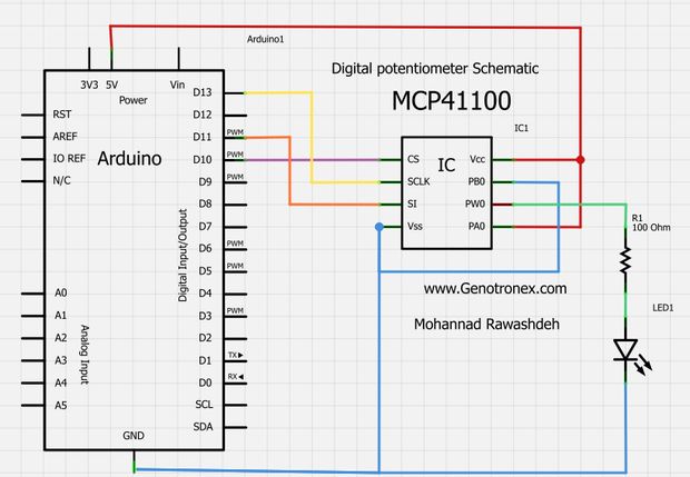
The pin Configuration for MCP41100 above , very easy .
This IC using SPI Protocol to communicate with Arduino Board .
Step 2: Calculate the resistance .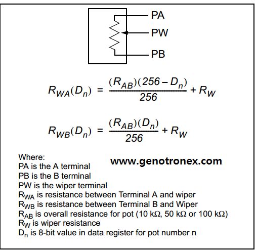
Ok , now we will look at this table , which is show who we can Calculate the Output resistance .
MCP41100 Have a sensitivity of 8bit , 256 taps for each potentiometer will taken from .
The MCP41100 Nominal resistane equal 100K ohm “Rab” and from the Datasheet , The wiper resistance is 125 ohm”Typical” ,
For example , if we write 222 to MCP41100 ,The resistance will equal :
Rwa= (100*10^3)*(256-222)/256 – 125 = 13.41K ohm .
Step 3: Arduino Code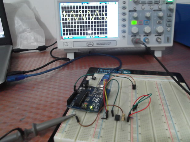
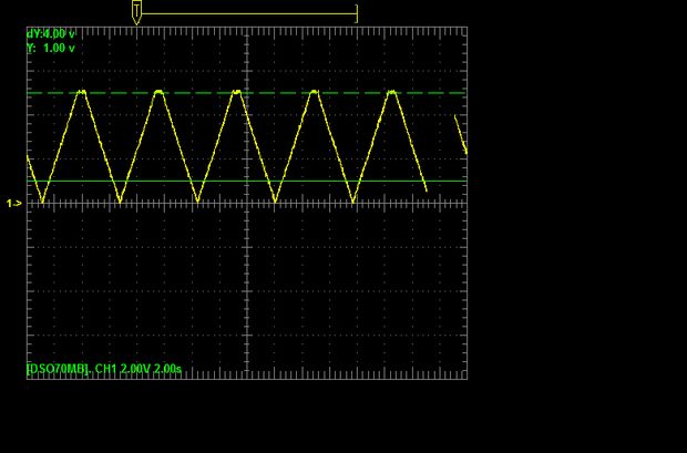 The arduino Code below :
/*
this program taken from arduino Example .
modified by By Mohannad Rawashdeh
http://www.genotronex.com
http://www.instructables.com/

This code used to control the digital potentiometer
MCP41100 connected to  arduino Board
CS >>> D10
SCLK >> D13
DI  >>> D11
PA0 TO VCC
PBO TO GND
PW0 TO led with resistor 100ohm .
*/
#include <SPI.h>
byte address = 0x11;
int CS= 10;
int i=0;

void setup()
{
pinMode (CS, OUTPUT);
SPI.begin();
// adjust high and low resistance of potentiometer
// adjust Highest Resistance .
digitalPotWrite(0x00);
delay(1000);

// adjust  wiper in the  Mid point  .
digitalPotWrite(0x80);
delay(1000);

// adjust Lowest Resistance .
digitalPotWrite(0xFF);
delay(1000);
}

void loop()
{
for (i = 0; i <= 255; i++)
{
digitalPotWrite(i);
delay(10);
}
delay(500);
for (i = 255; i >= 0; i--)
{
digitalPotWrite(i);
delay(10);
}
}

int digitalPotWrite(int value)
{
digitalWrite(CS, LOW);
SPI.transfer(address);
SPI.transfer(value);
digitalWrite(CS, HIGH);
Step 4: Simple applications :Motor drive controller and LED Controller
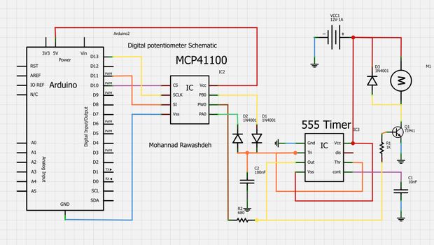 This Is a simple example to control the speed of DC Motor using555 timer , PWM Technique
the arduino Code :
/*
this program taken from arduino Example .
modified by By Mohannad Rawashdeh
http://www.genotronex.com
This code used to control the digital potentiometer
MCP41100 connected to  arduino Board
CS >>> D10
SCLK >> D13
DI  >>> D11
PA0 TO VCC
PBO TO GND
PW0 TO led with resistor 100ohm .
*/
#include <SPI.h>
byte address=0x11;
int CS= 10;

void setup()
{
pinMode (CS, OUTPUT);
SPI.begin();
// adjust high and low resistance of potentiometer
// adjust Highest Resistance .
digitalPotWrite(0x00);
delay(1000);

// adjust  wiper in the  Mid point  .
digitalPotWrite(0x80);
delay(1000);

// adjust Lowest Resistance .
digitalPotWrite(0xFF);
delay(1000);
}

void loop()
{
for (int i = 0; i <= 255; i++)
{
digitalPotWrite(i);
delay(10);
}
delay(1000);
for (int i = 255; i >= 0; i--)
{
digitalPotWrite(i);
delay(5);
}

}

int digitalPotWrite(int value)
{
digitalWrite(CS, LOW);
SPI.transfer(address);
SPI.transfer(value);
digitalWrite(CS, HIGH);
Video :
- What is the MCP41100 used for?
The MCP41100 is a digital potentiometer used to adjust resistance digitally for applications like volume control, amplifier gain/offset, and displacement transducers. - How does the Arduino communicate with the MCP41100?
The Arduino communicates with the MCP41100 using the SPI protocol. - Which Arduino pins are used to connect to the MCP41100 in the example?
CS to D10, SCLK to D13, and DI to D11. - How many steps or taps does the MCP41100 have?
The MCP41100 has 8-bit resolution with 256 taps. - What is the nominal resistance of the MCP41100 in the article?
The nominal resistance Rab is 100 K ohm. - What is the typical wiper resistance value mentioned?
The typical wiper resistance is 125 ohm. - How do you calculate the wiper resistance for a given code example?
The article gives an example: for code 222, Rwa = (100*10^3)*(256-222)/256 - 125 = 13.41 K ohm. - Can the MCP41100 be used to control LED brightness and motor speed?
Yes, the article shows simple applications controlling LED and DC motor speed using the MCP41100 with Arduino and a 555 PWM circuit. - What initial wiper positions are set in the example setup?
The example sets highest resistance (0x00), midpoint (0x80), and lowest resistance (0xFF) with delays between each.
