Summary of Arduino Based Vehicle Accident Alert System using GPS, GSM and Accelerometer
Summary (under 100 words): An Arduino-based vehicle accident alert system uses an ADXL335 accelerometer to detect sudden tilts, a SIM28ML GPS to obtain latitude, longitude and speed, and a SIM900A GSM module to send an SMS containing coordinates, speed (in knots) and a Google Maps link to a predefined number. The system calibrates the accelerometer, parses GPGGA/GPRMC NMEA strings to extract coordinates, and uses SoftwareSerial for module communication; an optional 16x2 LCD displays status and data.
Parts used in the Vehicle Accident Alert System:
- Arduino Uno
- GSM Module (SIM900A)
- GPS Module (SIM28ML)
- Accelerometer (ADXL335)
- 16x2 LCD
- Power Supply
- Connecting Wires
- 10 K-POT
- Breadboard or PCB
- Power supply 12v 1amp
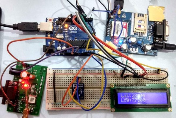
In our previous tutorials, we have learned about How to interface GPS module with Computer, how to build a Arduino GPS Clock and how to Track vehicle using GSM and GPS. Here in this project, we are going to build a Arduino based vehicle accident alert system using GPS, GSM and accelerometer. Accelerometer detects the sudden change in the axes of vehicle and GSM module sends the alert message on your Mobile Phone with the location of the accident. Location of accident is sent in the form of Google Map link, derived from the latitude and longitude from GPS module. The Message also contains the speed of vehicle in knots. See the Demo Video at the end. This Vehicle Accident alert project can also be used as a Tracking System and much more, by just making few changes in hardware and software.
Components Required:
- Arduino Uno
- GSM Module (SIM900A)
- GPS Module (SIM28ML)
- Accelerometer (ADXL335)
- 16×2 LCD
- Power Supply
- Connecting Wires
- 10 K-POT
- Breadboard or PCB
- Power supply 12v 1amp
Before going into Project, we will discuss about GPS, GSM and Accelerometer.
GPS Module and Its Working:
GPS stands for Global Positioning System and used to detect the Latitude and Longitude of any location on the Earth, with exact UTC time (Universal Time Coordinated). GPS module is used to track the location of accident in our project. This device receives the coordinates from the satellite for each and every second, with time and date. We have previously extracted $GPGGA string in Vehicle Tracking System to find the Latitude and Longitude Coordinates.
GPS module sends the data related to tracking position in real time, and it sends so many data in NMEA format (see the screenshot below). NMEA format consists several sentences, in which we only need one sentence. This sentence starts from $GPGGA and contains the coordinates, time and other useful information. This GPGGA is referred to Global Positioning System Fix Data. Know more about NMEA sentences and reading GPS data here.
We can extract coordinate from $GPGGA string by counting the commas in the string. Suppose you find $GPGGA string and stores it in an array, then Latitude can be found after two commas and Longitude can be found after four commas. Now, this latitude and longitude can be put in other arrays.
Below is the $GPGGA String, along with its description:
$GPGGA,104534.000,7791.0381,N,06727.4434,E,1,08,0.9,510.4,M,43.9,M,,*47
$GPGGA,HHMMSS.SSS,latitude,N,longitude,E,FQ,NOS,HDP,altitude,M,height,M,,checksum data
| Identifier | Description |
| $GPGGA | Global Positioning system fix data |
| HHMMSS.SSS | Time in hour minute seconds and milliseconds format. |
| Latitude | Latitude (Coordinate) |
| N | Direction N=North, S=South |
| Longitude | Longitude(Coordinate) |
| E | Direction E= East, W=West |
| FQ | Fix Quality Data |
| NOS | No. of Satellites being Used |
| HDP | Horizontal Dilution of Precision |
| Altitude | Altitude (meters above from sea level) |
| M | Meter |
| Height | Height |
| Checksum | Checksum Data |
GSM Module:
The SIM900 is a complete Quad-band GSM/GPRS Module which can be embedded easily used by customer or hobbyist. SIM900 GSM Module provides an industry-standard interface. SIM900 delivers GSM/GPRS 850/900/1800/1900MHz performance for voice, SMS, Data with low power consumption. It is easily available in the market.
- SIM900 designed by using single-chip processor integrating AMR926EJ-S core
- Quad – band GSM/GPRS module in small size.
- GPRS Enabled
AT Command:
AT means ATTENTION. This command is used to control GSM module. There are some commands for calling and messaging that we have used in many of our previous GSM projects with Arduino. For testing GSM Module we used AT command. After receiving AT Command GSM Module respond with OK. It means GSM module is working fine. Below is some AT commands we used here in this project:
ATE0 For echo off
AT+CNMI=2,2,0,0,0  <ENTER>       Auto opened message Receiving.  (No need to open message)
ATD<Mobile Number>; <ENTER>      making a call (ATD+919610126059;\r\n)
AT+CMGF=1 <ENTER>                Selecting Text mode
AT+CMGS=”Mobile Number” <ENTER>  Assigning recipient’s mobile number
>>Now we can write our message
>>After writing message
Ctrl+Z  send message command (26 in decimal).
ENTER=0x0d in HEX
(To learn more about GSM module, Check our various GSM projects with various microcontrollers here)
Accelerometer:
Pin Description of accelerometer:
- Vcc 5 volt supply should connect at this pin.
- X-OUT This pin gives an Analog output in x direction
- Y-OUT This pin give an Analog Output in y direction
- Z-OUT This pin gives an Analog Output in z direction
- GND Ground
- ST This pin used for set sensitivity of sensor
Also check our other projects using Accelerometer: Ping Pong Game using Arduino and Accelerometer Based Hand Gesture Controlled Robot.
Circuit Explanation:
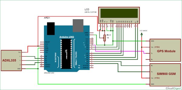
Circuit Connections of this Vehicle Accident Alert System Project is simple. Here Tx pin of GPS module is directly connected to digital pin number 10 of Arduino. By using Software Serial Library here, we have allowed serial communication on pin 10 and 11, and made them Rx and Tx respectively and left the Rx pin of GPS Module open. By default Pin 0 and 1 of Arduino are used for serial communication but by using the SoftwareSerial library, we can allow serial communication on other digital pins of the Arduino. 12 Volt supply is used to power the GPS Module.
GSM module’s Tx and Rx pins of are directly connected to pin D2 and D3 of Arduino. For GSM interfacing, here we have also used software serial library. GSM module is also powered by 12v supply. An optional LCD’s data pins D4, D5, D6, and D7 are connected to pin number 6, 7, 8, and 9 of Arduino. Command pin RS and EN of LCD are connected with pin number 4 and 5 of Arduino and RW pin is directly connected with ground. A Potentiometer is also used for setting contrast or brightness of LCD.
An Accelerometer is added in this system for detecting an accident and its x,y, and z-axis ADC output pins are directly connected to Arduino ADC pin A1, A2, and A3.
Working Explanation:
In this project, Arduino is used for controlling whole the process with a GPS Receiver and GSM module. GPS Receiver is used for detecting coordinates of the vehicle, GSM module is used for sending the alert SMS with the coordinates and the link to Google Map. Accelerometer namely ADXL335 is used for detecting accident or sudden change in any axis. And an optional 16×2 LCD is also used for displaying status messages or coordinates. We have used GPS Module SIM28ML and GSM Module SIM900A.
When we are ready with our hardware after programming, we can install it in our vehicle and power it up. Now whenever there is an accident, the car gets tilt and accelerometer changes his axis values. These values read by Arduino and checks if any change occurs in any axis. If any change occurs then Arduino reads coordinates by extracting $GPGGA String from GPS module data (GPS working explained above) and send SMS to the predefined number to the police or ambulance or family member with the location coordinates of accident place. The message also contains a Google Map link to the accident location, so that location can be easily tracked. When we receive the message then we only need to click the link and we will redirect to the Google map and then we can see the exact location of the vehicle. Speed of Vehicle, in knots (1.852 KPH), is also sent in the SMS and displayed on the LCD panel. Check the full Demo Video below the Project.
Here in this project, we can set the sensitivity of Accelerometer by putting min and max value in the code.
Here in the demo have used given values:
#define minVal -50
#define MaxVal 50
But for better results you can use 200 in place of 50, or can set according to your requirement.
Programming Explanation:
Complete Program has been given below in Code section; here we are explaining its various functions in brief.
First we have included all the required libraries or headers files and declared various variables for calculations and storing data temporary.
After this, we have created a function void initModule(String cmd, char *res, int t) to initialize the GSM module and checking its response using AT commands.
void initModule(String cmd, char *res, int t)
{
  while(1)
  {
    Serial.println(cmd);
    Serial1.println(cmd);
    delay(100);
    while(Serial1.available()>0)
    {
       if(Serial1.find(res))
       {
        Serial.println(res);
        delay(t);
        return;
       }

       else
       {
        Serial.println("Error");
       }
    }
    delay(t);
  }
}
After this, in void setup() function, we have initialized hardware and software serial communication, LCD, GPS, GSM module and accelerometer.
void setup()
{
  Serial1.begin(9600);
  Serial.begin(9600);
  lcd.begin(16,2);
  lcd.print("Accident Alert  ");
  lcd.setCursor(0,1);
  lcd.print("     System     ");
  delay(2000);
  lcd.clear();
  .... ......
  ...... .....
Accelerometer calibration process is also done in setup loop. In this, we have taken some samples and then find the average values for the x-axis, y-axis, and z-axis. And store them in a variable. Then we have used these sample values to read changes in accelerometer axis when vehicle gets tilt (accident).
  lcd.print("Callibrating ");
  lcd.setCursor(0,1);
  lcd.print("Acceleromiter");
  for(int i=0;i<samples;i++)
  {
    xsample+=analogRead(x);
    ysample+=analogRead(y);
    zsample+=analogRead(z);
  }

  xsample/=samples;
  ysample/=samples;
  zsample/=samples;

  Serial.println(xsample);
  Serial.println(ysample);
  Serial.println(zsample);
After this, in the void loop() function, we have read accelerometer axis values and done a calculation to extract changes with the help of samples that are taken in Calibration. Now if any changes are more or less then defined level then Arduino sends a message to the predefined number.
void loop()
{
    int value1=analogRead(x);
    int value2=analogRead(y);
    int value3=analogRead(z);

    int xValue=xsample-value1;
    int yValue=ysample-value2;
    int zValue=zsample-value3;

    Serial.print("x=");
    Serial.println(xValue);
    Serial.print("y=");
    Serial.println(yValue);
    Serial.print("z=");
    Serial.println(zValue);
    ..... .....
    ........ ...
Here we have also created some other function for various puposes like void gpsEvent() to get GPS coordinates, void coordinate2dec() for extracting coordinates from the GPS string and convert them into Decimal values, void show_coordinate() for displaying values over serial monitor and LCD, and finally the void Send() for sending alert SMS to the predefined number.
Complete code and demo video is given below, you can check all the functions in the code.
#include<SoftwareSerial.h>
SoftwareSerial Serial1(2,3); //make RX arduino line is pin 2, make TX arduino line is pin 3.
SoftwareSerial gps(10,11);
#include<LiquidCrystal.h>
LiquidCrystal lcd(4,5,6,7,8,9);
#define x A1
#define y A2
#define z A3
int xsample=0;
int ysample=0;
int zsample=0;
#define samples 10
#define minVal -50
#define MaxVal 50
int i=0,k=0;
int gps_status=0;
float latitude=0;
float logitude=0;
String Speed=””;
String gpsString=””;
char *test=”$GPRMC”;
void initModule(String cmd, char *res, int t)
{
while(1)
{
Serial.println(cmd);
Serial1.println(cmd);
delay(100);
while(Serial1.available()>0)
{
if(Serial1.find(res))
{
Serial.println(res);
delay(t);
return;
}
else
{
Serial.println(“Error”);
}
}
delay(t);
}
}
void setup()
{
Serial1.begin(9600);
Serial.begin(9600);
lcd.begin(16,2);
lcd.print(“Accident Alert “);
lcd.setCursor(0,1);
lcd.print(” System “);
delay(2000);
lcd.clear();
lcd.print(“Initializing”);
lcd.setCursor(0,1);
lcd.print(“Please Wait…”);
delay(1000);
Serial.println(“Initializing….”);
initModule(“AT”,”OK”,1000);
initModule(“ATE1″,”OK”,1000);
initModule(“AT+CPIN?”,”READY”,1000);
initModule(“AT+CMGF=1″,”OK”,1000);
initModule(“AT+CNMI=2,2,0,0,0″,”OK”,1000);
Serial.println(“Initialized Successfully”);
lcd.clear();
lcd.print(“Initialized”);
lcd.setCursor(0,1);
lcd.print(“Successfully”);
delay(2000);
lcd.clear();
lcd.print(“Callibrating “);
lcd.setCursor(0,1);
lcd.print(“Acceleromiter”);
for(int i=0;i<samples;i++)
{
xsample+=analogRead(x);
ysample+=analogRead(y);
zsample+=analogRead(z);
}
xsample/=samples;
ysample/=samples;
zsample/=samples;
Serial.println(xsample);
Serial.println(ysample);
Serial.println(zsample);
delay(1000);
lcd.clear();
lcd.print(“Waiting For GPS”);
lcd.setCursor(0,1);
lcd.print(” Signal “);
delay(2000);
gps.begin(9600);
get_gps();
show_coordinate();
delay(2000);
lcd.clear();
lcd.print(“GPS is Ready”);
delay(1000);
lcd.clear();
lcd.print(“System Ready”);
Serial.println(“System Ready..”);
}
void loop()
{
int value1=analogRead(x);
int value2=analogRead(y);
int value3=analogRead(z);
int xValue=xsample-value1;
int yValue=ysample-value2;
int zValue=zsample-value3;
Serial.print(“x=”);
Serial.println(xValue);
Serial.print(“y=”);
Serial.println(yValue);
Serial.print(“z=”);
Serial.println(zValue);
if(xValue < minVal || xValue > MaxVal || yValue < minVal || yValue > MaxVal || zValue < minVal || zValue > MaxVal)
{
get_gps();
show_coordinate();
lcd.clear();
lcd.print(“Sending SMS “);
Serial.println(“Sending SMS”);
Send();
Serial.println(“SMS Sent”);
delay(2000);
lcd.clear();
lcd.print(“System Ready”);
}
}
void gpsEvent()
{
gpsString=””;
while(1)
{
while (gps.available()>0) //Serial incoming data from GPS
{
char inChar = (char)gps.read();
gpsString+= inChar; //store incoming data from GPS to temparary string str[]
i++;
// Serial.print(inChar);
if (i < 7)
{
if(gpsString[i-1] != test[i-1]) //check for right string
{
i=0;
gpsString=””;
}
}
if(inChar==’\r’)
{
if(i>60)
{
gps_status=1;
break;
}
else
{
i=0;
}
}
}
if(gps_status)
break;
}
}
void get_gps()
{
lcd.clear();
lcd.print(“Getting GPS Data”);
lcd.setCursor(0,1);
lcd.print(“Please Wait…..”);
gps_status=0;
int x=0;
while(gps_status==0)
{
gpsEvent();
int str_lenth=i;
coordinate2dec();
i=0;x=0;
str_lenth=0;
}
}
void show_coordinate()
{
lcd.clear();
lcd.print(“Lat:”);
lcd.print(latitude);
lcd.setCursor(0,1);
lcd.print(“Log:”);
lcd.print(logitude);
Serial.print(“Latitude:”);
Serial.println(latitude);
Serial.print(“Longitude:”);
Serial.println(logitude);
Serial.print(“Speed(in knots)=”);
Serial.println(Speed);
delay(2000);
lcd.clear();
lcd.print(“Speed(Knots):”);
lcd.setCursor(0,1);
lcd.print(Speed);
}
void coordinate2dec()
{
String lat_degree=””;
for(i=20;i<=21;i++)
lat_degree+=gpsString[i];
String lat_minut=””;
for(i=22;i<=28;i++)
lat_minut+=gpsString[i];
String log_degree=””;
for(i=32;i<=34;i++)
log_degree+=gpsString[i];
String log_minut=””;
for(i=35;i<=41;i++)
log_minut+=gpsString[i];
Speed=””;
for(i=45;i<48;i++) //extract longitude from string
Speed+=gpsString[i];
float minut= lat_minut.toFloat();
minut=minut/60;
float degree=lat_degree.toFloat();
latitude=degree+minut;
minut= log_minut.toFloat();
minut=minut/60;
degree=log_degree.toFloat();
logitude=degree+minut;
}
void Send()
{
Serial1.println(“AT”);
delay(500);
serialPrint();
Serial1.println(“AT+CMGF=1”);
delay(500);
serialPrint();
Serial1.print(“AT+CMGS=”);
Serial1.print(‘”‘);
Serial1.print(“9821757249”); //mobile no. for SMS alert
Serial1.println(‘”‘);
delay(500);
serialPrint();
Serial1.print(“Latitude:”);
Serial1.println(latitude);
delay(500);
serialPrint();
Serial1.print(” longitude:”);
Serial1.println(logitude);
delay(500);
serialPrint();
Serial1.print(” Speed:”);
Serial1.print(Speed);
Serial1.println(“Knots”);
delay(500);
serialPrint();
Serial1.print(“http://maps.google.com/maps?&z=15&mrt=yp&t=k&q=“);
Serial1.print(latitude,6);
Serial1.print(“+”); //28.612953, 77.231545 //28.612953,77.2293563
Serial1.print(logitude,6);
Serial1.write(26);
delay(2000);
serialPrint();
}
void serialPrint()
{
while(Serial1.available()>0)
{
Serial.print(Serial1.read());
}
}
Video:
Source: Arduino Based Vehicle Accident Alert System using GPS, GSM and Accelerometer
- How does the system detect an accident?
The ADXL335 accelerometer monitors sudden changes in x, y, or z axes and the Arduino compares calibrated axis deviations to threshold values to detect an accident. - How are coordinates obtained from the GPS module?
The Arduino reads NMEA sentences from the GPS, finds the GPGGA/GPRMC string, and extracts latitude and longitude by parsing specific comma-separated fields. - Can the system send the accident location to a mobile phone?
Yes, the SIM900A GSM module sends an SMS to a predefined number containing latitude, longitude, speed, and a Google Maps link. - What serial method is used to communicate with GPS and GSM?
The project uses the SoftwareSerial library to assign serial communication to digital pins (GPS on 10,11 and GSM on 2,3) instead of hardware pins 0 and 1. - Does the SMS include vehicle speed?
Yes, the SMS includes the vehicle speed in knots extracted from the GPS string and displayed on the LCD. - How is accelerometer sensitivity set?
Sensitivity is set in code via minVal and MaxVal defines; example values used are -50 and 50 but can be increased (e.g., 200) per requirement. - Is an LCD required for the system to work?
No, the 16x2 LCD is optional and used only to display status messages, coordinates, and speed. - What power supply is recommended?
The project specifies a 12V 1A power supply to power modules like GPS and GSM.