
Summary of Arduino Based Tone Generator
This project builds a tone generator using an Arduino Uno where eight buttons control sound intensity via PWM, keeping frequency constant while varying duty cycles to alter volume. The circuit uses capacitors for noise filtering and specific PWM pins to drive a buzzer, creating a simple piano-like interface with smooth tonal variations up to 20 levels.
Parts used in the Arduino Tone Generator:
- Arduino Uno
- Power supply (5v)
- 1000 uF capacitor
- 100 nF capacitor
- Buzzer
- Buttons (8 pieces)
In this project we will develop a tone generator using Arduino Uno. We will have buttons interfaced with the UNO and each one of them generates different intensity of tone. The frequency of tone generated by the UNO is same at every internal. It’s the intensity of the sound which changes with each press. This is the one of the easiest way to make a piano with Arduino Uno. Also check this Piano circuit.
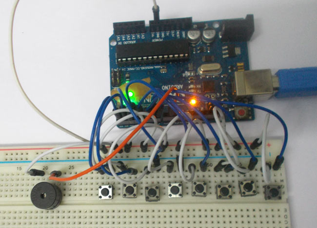
The tones can be increased up to 20. This gives the best tone variation and much smoother changes. The intensity of the tone is changed by PWM (Pulse Width Modulation). An example of PWM is shown in below graph.
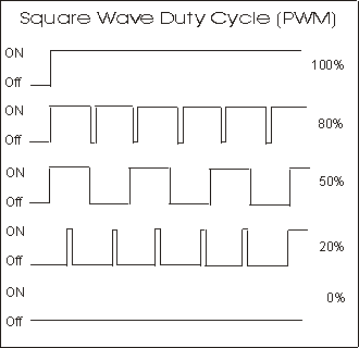
PWM, the frequency of signal or the time period of signal (Ton + Toff) is always constant. Only the ratio of TURN ON and TURN OFF time changes. For example in the second graph in above figure, the TURN ON time is 80% and TURN OFF time is 20% of complete duration.
In the third graph, the TURN ON time is 50% and TURN OFF time is 50% of complete duration. So in first case we have a duty ratio of 80% and in second case we have a duty ratio of 20%.
With this change in duty ratio we have a change in Vrms (Root Mean Square value of Voltage), when this voltage is given to the buzzer it makes a different noise whenever there is a change in duty ratio.
We are going to program the UNO to provide a PWM signal of different duty ratio for each of buttons. So we have a tone generator at hand which generates a different tone with each button press.
Components Required
Hardware: Arduino Uno, Power supply (5v), 1000 uF capacitor, 100 nF capacitor, Buzzer, buttons (8 pieces).
Software: AURDINO nightly or Atmel studio 6.2
Circuit Diagram and Working Explanation
The circuit for tone generator is shown in below diagram.
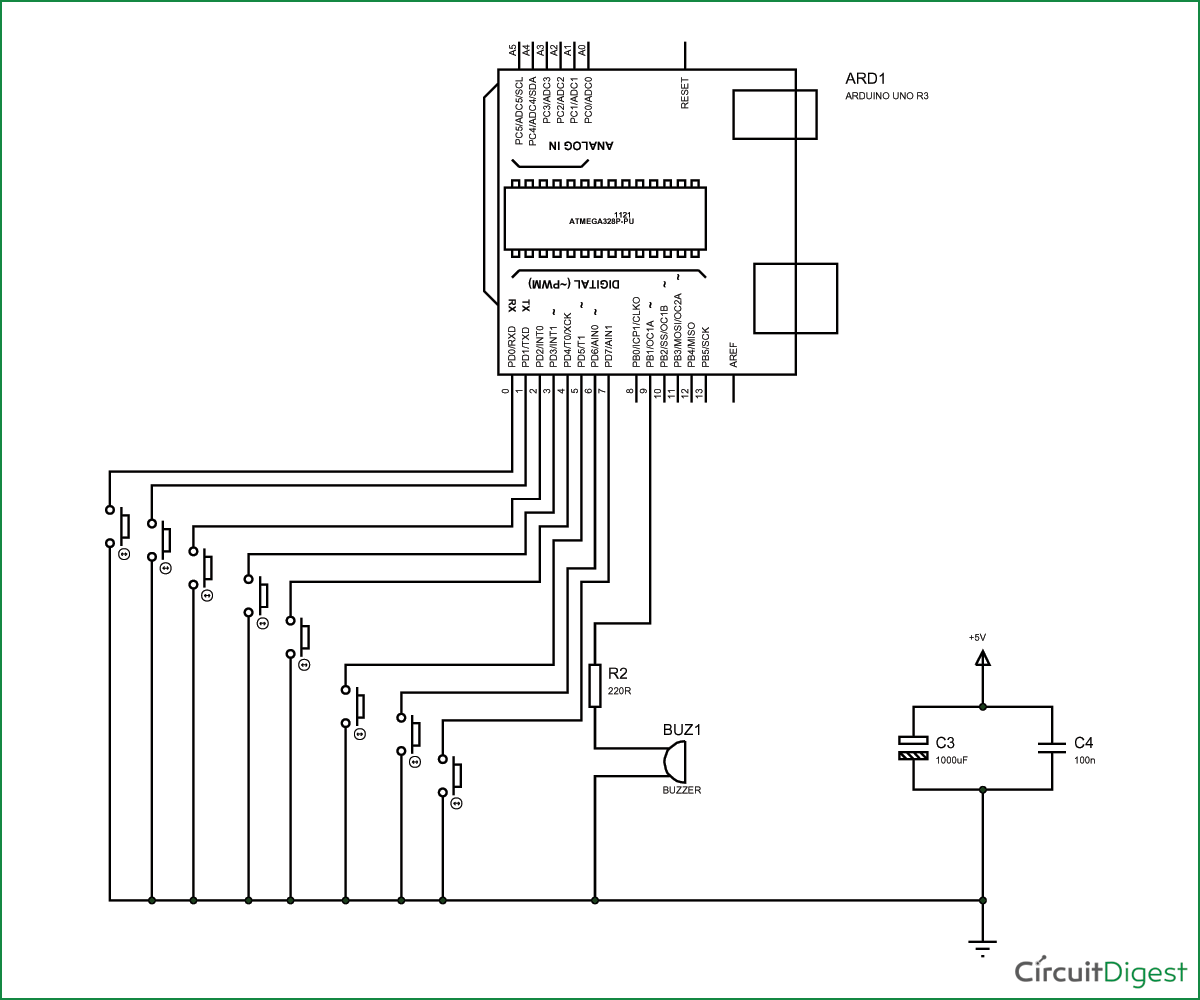
To filter out the noise from supply voltage capacitors are placed across terminals as shown in the diagram.
The PWM of Arduino Uno can achieved at any of pins symbolized as “ ~ ” on the PCB board. There are six PWM channels in UNO. However we cannot use PWM pins established over the PINS 0-7, as the PINS are preferred for buttons interface.
Read More: Arduino Based Tone Generator
-
How does the intensity of the tone change?
The intensity changes by using Pulse Width Modulation (PWM) to vary the duty ratio, which alters the Vrms voltage given to the buzzer. -
Can the tones be increased up to 20?
Yes, the tones can be increased up to 20, providing the best tone variation and much smoother changes. -
Which pins should be avoided for PWM output?
You cannot use PWM pins established over PINS 0-7 because these pins are preferred for button interfaces. -
What is the purpose of the capacitors in the circuit?
Capacitors are placed across terminals to filter out noise from the supply voltage. -
Does the frequency of the generated tone change?
No, the frequency of the tone generated by the UNO remains the same at every internal; only the intensity changes. -
How many PWM channels are available on the UNO?
There are six PWM channels in the UNO that can be achieved at any pins symbolized as ~ on the PCB board. -
What software options are required for this project?
The required software includes AURDINO nightly or Atmel studio 6.2.
