Summary of Arduino-Based Smart Parking System with IR Sensor Integration
The article explains building a Smart Parking System using Arduino, IR sensors, and a servo motor to automate parking slot management. The system detects car entry/exit and slot occupancy with IR sensors, controls a servo-driven gate, and displays slot status on an LCD. It helps drivers identify available slots in real-time, reducing parking frustration in congested areas. The project includes a detailed block diagram, circuit schematic, component lists, working principle, and Arduino code to implement the system managing up to four parking slots with entry/exit control.
Parts used in the Smart Parking System Project:
- Arduino Nano or Arduino Uno
- USB Cable for Arduino
- IR Sensor (6 units)
- SG90 Servo Motor
- 9V power supply
- PCB board or Breadboard
- Connecting wires
- LCD (LiquidCrystal_I2C)
Good day, ElectroDuino community! We are delighted to have all of you back to our site. In today’s session we will be learning the Smart Parking System Project based on Arduino, IR Sensors and servo Motors. The above considerations of explaining the project concept, thinking through the approach, using a block diagram, determining components, using a circuit diagram, explaining how the system operates, and explaining how the Arduino code works will be discussed during our conversation. We aim to give everyone an overview of how this automated parking solution is designed and programmed from start to finish using these technologies. Let’s get started!

This endeavor is made possible through the generous sponsorship of pcbway.com, a leading provider of professional-grade PCB prototype services. Their offer includes 10 top-tier PCBs for a mere $5. To avail of this offer, simply register on their website, input your specifications regarding Dimensions, Layers, Thickness, Color, and Quantity, and then upload your Gerber files to place your order promptly. With a swift turnaround time of 24 hours, pcbway.com ensures the rapid production of your PCB prototypes.
Don’t miss out on this opportunity to acquire high-quality PCB prototypes swiftly from pcbway.com. Order now to elevate your project to new heights!
Introduction
In today’s urban landscape, locating available parking spaces poses a significant challenge due to congestion. The volume of vehicles on the roads far exceeds the available parking capacity. Upon entering a parking area, individuals often encounter the frustrating scenario of insufficient vacant slots to accommodate their cars, leading to time wastage. Additionally, navigating through large parking facilities to identify empty spots adds to the confusion and further consumes valuable time. Many of us have experienced these twin issues, which underscore the need for efficient parking management systems in all parking facilities. These systems aim to offer hassle-free and straightforward parking experiences.
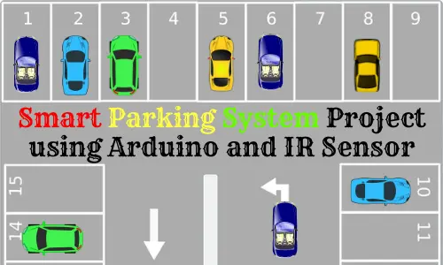
To address this pressing concern, we will outline a “Smart Parking System Project” in this tutorial. This project is intended to eliminate some of the mentioned difficulties by offering the driver a real-time opportunity to see whether there is space for parking and hence saves time during the parking process.
Smart Parking System Project Concept
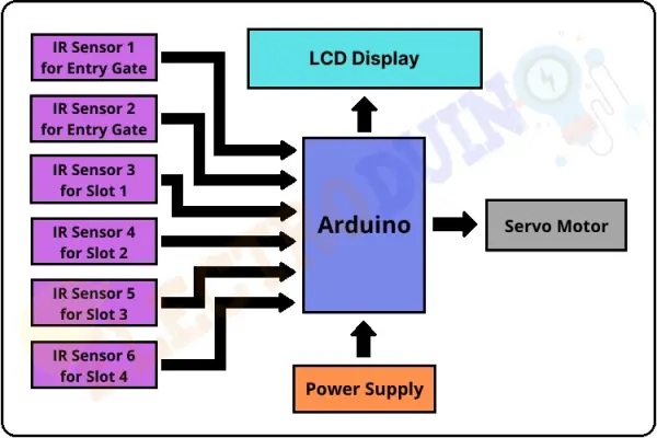
This concept of the smart parking system involves the use of an Arduino microcontroller, six IR sensors, a servo motor, and an LCD. The Arduino Board: The Arduino Board is used for controlling the whole central system of Green Travel. Two IR sensors are positioned at the entry and exit points to detect vehicles entering and leaving the parking area, while the remaining four sensors monitor parking slot availability. The servo motor operates the entry and exit gates. Additionally, an LCD at the entrance indicates the availability of parking slots.
Upon a vehicle’s arrival at the parking gate, the display continually updates to reflect the number of vacant slots. If slots are available, the system activates the servo motor to open the entry gate. As a vehicle occupies a slot, the display indicates that the slot is filled.
In the event that all parking slots are occupied, the system displays a message indicating full capacity and does not open the gate.
Block Diagram of Smart Parking System Project

Components Required
| Components Name | Quantity |
| Arduino Nano or Arduino Uno | 1 |
| USB Cable for Arduino | 1 |
| IR Sensor | 6 |
| Sg90 Servo Motor | 1 |
| 9V power supply | 1 |
| PCB board or Breadboard | 1 |
| Connecting wires | As required in the circuit diagram |
Tools Required
| Tools Name | Quantity |
| Soldering Iron | 1 |
| Soldering wire | 1 |
| Soldering flux | 1 |
| Soldering stand | 1 |
| Multimeter | 1 |
| Desoldering pump | 1 |
| Wirecutter | 1 |
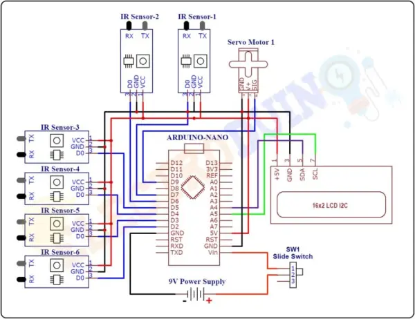
Circuit Diagram of Smart Parking System Project using Arduino and IR Sensor

Working Principle
Once the circuit diagram of the entire system has been followed and the code for the Arduino board has been uploaded, place the sensors and the servo motor properly.
This project as has been illustrated entails four parking slots, and the IR sensors 3, 4, 5 and 6 are located at slots 1,2,3 and 4 respectively. The first IR sensors should be placed at the entry gate and the second one at the exit gate The common entry and exit gate control should be done by servo motor. Also, there is an LCD display installed beside the entry gate collaborating with Australian Local Health District.
The system utilizes IR sensors 3, 4, 5, and 6 to determine parking slot occupancy and IR sensors 1 and 2 to detect vehicle arrivals at the gate.
Initially, when all parking slots are vacant, the LCD indicates that all slots are empty.
Upon a vehicle’s arrival at the parking gate, IR sensor 1 detects it, allowing the vehicle to enter by opening the servo barrier. Once the vehicle occupies a slot, the LED display indicates that the slot is now occupied. This system automatically accommodates up to four vehicles.
If the parking slots are all occupied, the system closes the entrance gate servo barrier and displays that slots 1 through 4 are full.
When a vehicle leaves a slot and approaches the gate, IR sensor 2 detects it, prompting the system to open the servo barrier. The LED display then indicates that the slot is vacant, allowing for the entry of a new vehicle.
Arduino Code
#include <Servo.h> //includes the servo library
#include <Wire.h>
#include <LiquidCrystal_I2C.h> //includes LiquidCrystal_I2C library
LiquidCrystal_I2C lcd(0x27, 20, 4);

Servo myservo;

#define ir_enter 2
#define ir_back  4

#define ir_car1 5
#define ir_car2 6
#define ir_car3 7
#define ir_car4 8

int S1=0, S2=0, S3=0, S4=0 ;
int flag1=0, flag2=0;
int slot = 6;

void setup(){
Serial.begin(9600);
// initialize digital pins as input.
pinMode(ir_car1, INPUT);
pinMode(ir_car2, INPUT);
pinMode(ir_car3, INPUT);
pinMode(ir_car4, INPUT);

pinMode(ir_enter, INPUT);
pinMode(ir_back, INPUT);

myservo.attach(9); // Servo motor pin connected to D9
myservo.write(90); // sets the servo at 0 degree position

// Print text on display
lcd.begin(20, 4);
lcd.setCursor (0,1);
lcd.print("    Smart Car   ");
lcd.setCursor (0,2);
lcd.print(" Parking System ");
delay (2000);
lcd.clear();

Read_Sensor();

int total = S1+S2+S3+S4;
slot = slot-total;
}

void loop()
{

 Read_Sensor();

 lcd.setCursor (0,0);
 lcd.print("   Have Slot: ");
 lcd.print(slot);
 lcd.print("    ");

 lcd.setCursor (0,1);
  if(S1==1)
   {
    lcd.print("S1:Fill ");
   }
  else
   {
    lcd.print("S1:Empty");
   }

 lcd.setCursor (10,1);
  if(S2==1)
   {
    lcd.print("S2:Fill ");
    }
  else
   {
    lcd.print("S2:Empty");
    }

 lcd.setCursor (0,2);
  if(S3==1)
   {
    lcd.print("S3:Fill ");
    }
  else
   {
    lcd.print("S3:Empty");
    }

 lcd.setCursor (10,2);
  if(S4==1)
   {
    lcd.print("S4:Fill ");
    }
  else
   {
    lcd.print("S4:Empty");
    }

/* Servo Motor Control
***********************/
  if(digitalRead (ir_enter) == 0 && flag1==0) // read degital data from IR sensor1
   {
    if(slot>0)
     {
      flag1=1;
      if(flag2==0)
       {
        myservo.write(180);
        slot = slot-1;
        }
     }
    else
     {
      lcd.setCursor (0,0);
      lcd.print(" Sorry Parking Full ");
      delay(1500);
      }
   }

  if(digitalRead (ir_back) == 0 && flag2==0) // read degital data from IR sensor2
   {
    flag2=1;
    if(flag1==0)
     {
      myservo.write(180); // sets the servo at 180 degree position
      slot = slot+1;
      }
   }

  if(flag1==1 && flag2==1)
   {
    delay (1000);
    myservo.write(90); // sets the servo at 90 degree position
    flag1=0, flag2=0;
    }
    delay(1);
}

void Read_Sensor()
{
 S1=0, S2=0, S3=0, S4=0;
 if(digitalRead(ir_car1) == 0){S1=1;} // read degital data from IR sensor3
 if(digitalRead(ir_car2) == 0){S2=1;} // read degital data from IR sensor4
 if(digitalRead(ir_car3) == 0){S3=1;} // read degital data from IR sensor5
 if(digitalRead(ir_car4) == 0){S4=1;} // read degital data from IR sensor6
}