
Summary of Arduino Based Programmable Digital Data Display
This project demonstrates an Arduino-based programmable digital display that shows messages on a 16×2 LCD screen via Bluetooth. Users type text on an Android smartphone using the Blue Term app, which transmits data to an HC-05 module connected to the Arduino. The Arduino processes this input and updates the LCD accordingly, making it ideal for token displays or restaurant order boards.
Parts used in the Arduino Based Programmable Digital Data Display:
- Arduino Uno board
- HC-05 Bluetooth module
- 16×2 LCD module
- Android smartphone
- Blue Term application
 LCDs are widely used in applications like token-display machines in smalls and supermarkets, order number displays in restaurants and café, and so on. The project presented here demonstrates the working of Arduino based message display on LCD using Bluetooth.
Circuit and working
This circuit uses Arduino board that accepts data via HC-05 Bluetooth module from various types of gadgets like Android based smartphones. Arduino is the heart of this programmable display. The circuit is shown in Fig. 1.
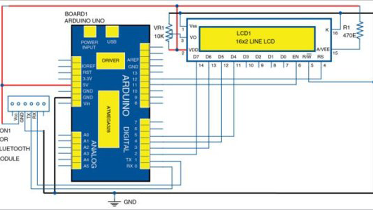
Circuit diagram of Arduino based programmable digital data display
The power supply is applied through the power input connector (not shown here). However, the same can be provided through the USB port to drive Arduino and LCD display.
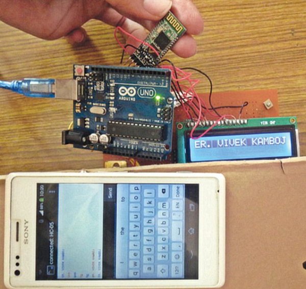
Author’s prototype of Arduino based programmable digital data display
In this application, the Bluetooth module acts as both transmitter and receiver, and is compatible with most smartphones. Different port pins of Arduino are used to drive the 16×2 LCD as shown in the circuit.
The message typed by the user on the Android based smartphone is received by the Bluetooth module and transmitted at its Tx pin, which is connected to port pin 0 (Rx) of Arduino. Similarly, Rx pin of the Bluetooth module is connected to port pin 1 (Tx) of Arduino.
In this manner data communication takes place between the user and Arduino board.
Software program
Circuit operation is performed using the software program loaded into the internal memory of Arduino board. The program implements all the required functionalities including user inputs through the smartphones by displaying messages on the LCD.
Launch Arduino software and select the correct COM port and Arduino board, and write Arduino sketch (program).The program is given below for reference:
[stextbox id=”info”]#include LiquidCrystal lcd(12, 11, 5, 4, 3, 2);
String inData;
void setup() {
Serial.begin(9600);
lcd.begin(16, 2);
lcd.print(“Welcome!”);
delay(3000);
lcd.clear();
}
void loop() {
int i=0;
char commandbuffer[100];
if(Serial.available()){
delay(100);
while( Serial.available() && i< 99) { commandbuffer[i++] = Serial.read(); } commandbuffer[i++]=’\0’; } if(i>0)
Serial.println((char*)commandbuffer);
lcd.print((char*)commandbuffer);
delay(1000);
lcd.clear();
}
Upload the source code to Arduino board.
Hardware setup
Components required for the project are Arduino Uno, HC-05 Bluetooth module, LCD module and Android smartphone.
Connect Bluetooth module. Connect Bluetooth module to Arduino. Connections of Bluetooth module with Arduino are mentioned below:
[stextbox id=”info”]Bluetooth module Arduino board
TX Pin 0 (Rx)
RX Pin 1 (Tx)
VCC +5V
GND GND
Connect LCD. Connect the LCD module to Arduino. Refer circuit diagram (Fig. 1) for connections. Turn on your Arduino and check if the LCD is working properly. You will see some black pixels on the screen.
Testing
To display the message on the LCD using the Android based smartphone, download Blue Term application from Google Play Store. Run it and HC-05 Bluetooth module will be detected by your smartphone. Pair your smartphone with HC-05. You can now type the desired message on your smartphone, followed by pressing Enter for transmission to HC-05 connected to Arduino. The message will be displayed on the LCD screen.
Author’s prototype is shown in Fig. 2.
Download PCB and component layout PDFs: Click here
Download Source Folder
Read More Detail:Arduino Based Programmable Digital Data Display
- How does the Bluetooth module connect to the Arduino?
The TX pin of the Bluetooth module connects to Pin 0 (Rx) of Arduino, and the RX pin connects to Pin 1 (Tx). - Can I power the circuit through the USB port?
Yes, the same power can be provided through the USB port to drive the Arduino and LCD display. - What application is required on the smartphone?
You must download the Blue Term application from the Google Play Store. - How do you send a message to the display?
Type the desired message on the smartphone and press Enter for transmission to the HC-05 module. - What is the role of the Arduino in this project?
The Arduino acts as the heart of the programmable display, accepting data and driving the LCD. - Does the Bluetooth module act as a transmitter or receiver?
The Bluetooth module acts as both a transmitter and receiver compatible with most smartphones. - What are the specific pin connections for VCC and GND?
The VCC of the Bluetooth module connects to +5V, and GND connects to GND on the Arduino board.
