WHAT?
Hi!
I’ve made bleeding LED stairs! It’s a new Instructables leveraging some hardware installation I had done already from a previous I’ble from mine. I made a RED animation that resembles blood drops, perfect to be activated automatic during those trick or treat moments!
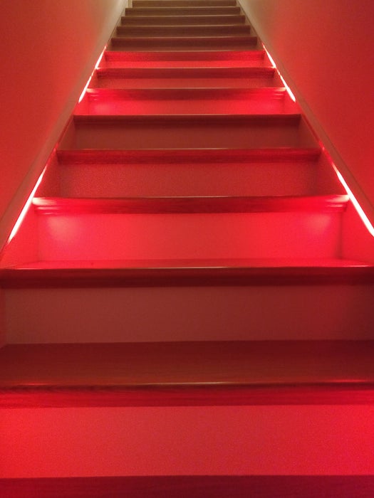
As soon as you approach the stairs “drops of blood” appear from random places on the stairs and start going down, leaving traces of blood along their ways, that gradually disappear. The number of drops is a parameter in the Arduino sketch.
The realism of the effect is enhanced by the random speed of the drops: they’ don’t go down linearly, but they slow down and speed up as liquid drops do when going down a surface (like blood as well).
As I said, I have leveraged some existing hardware installation, however the programming (Arduino sketch) is entirely new, plus some new wooden finish to make them fully embedded with the stairs. The existing hardware installation is replicated in steps 1 and 2, and, for completeness, is taken from here:
https://www.instructables.com/id/Automatic-IoT-Sta…
Steps 3, 4, and 5 are brand new, also the below shopping list is different.
WHY?
The stairs had already some animations, but I was missing something specific for Halloween. The stairs are visible from outside the main door, so it’s pretty cool to scare off all those monsters by showing them some true blood! 🙂
SHOPPING LIST
I used the following components, scroll down for the building steps:
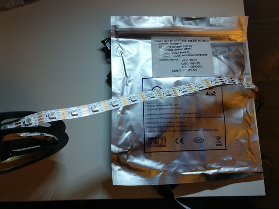
1) 2 x 4m ws2813 rgb LED strips:
https://www.aliexpress.com/wholesale?catId=0&initi…
get the non waterproof version, with 60 leds/m. Also, I found a cheaper 5m version and just cut 1m from the end of both the strips. Note you can do this with ws2812 and ws2812b LEDs as well, the light will be exactly the same and these are cheaper. The ws2813 are just more reliable, as they have a redundant data connection, so if you break one LED, the rest of the strip will keep working. These were roughly 27$ / 25€ each.
2) 4 x 2m U-line aluminum profiles, 14mm x 13mm:
https://www.ebay.ie/itm/New-2-METERS-U-LINE-Alumin…
These were 20€ each, roughly 22$. I have also bought the terminal caps and the fitting screws. The screws couldn’t be installed on the side I needed them, they are supposed to be installed on the side opposite to the diffuser, so they were of no use for me. Instead, thanks to the slope of the stairs and some friction provided by the skirting board, some pieces of bi-adhesive scotch tape was enough to fit the profiles over the skirting boards.
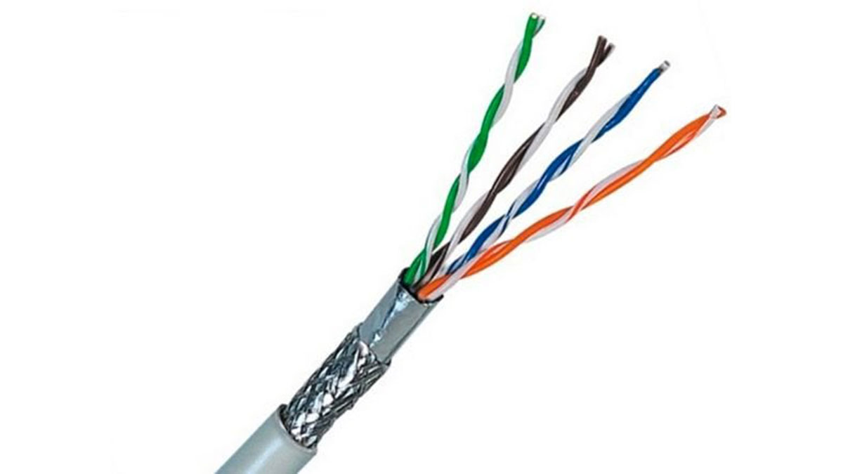
3) 2 x cat-5 Ethernet cables :
https://www.aliexpress.com/item/Vention-Ethernet-C…
I have no idea which length was used here, I guess around 2m, the electrician and the carpenter installed the cables under the floor, going from the skirting boards of the stairs, to the room with the hotpress. Note that too long cables will reduce the current and you’ll need some more sophisticated setup to provide the correct current and to avoid breaking the data connection.
4) spare assorted dupont cables:
https://www.aliexpress.com/wholesale?catId=0&initi…
5) as wifi-enabled micro-controller, I have used the first version of the Wemos D1, now discontinued, which you can still find online:
https://www.aliexpress.com/wholesale?catId=0&initi…
For future readers, if you don’t find it, version R2 of the Wemos D1 should work as well.
6) 2 x PIR motion sensors for Arduino:
https://www.aliexpress.com/wholesale?catId=0&initi…
7) one 5v, 40a, 200w power supply:
https://www.aliexpress.com/wholesale?catId=0&initi…
This was 21.5£, roughly 25€ or 27$. You probably need less than 40A, but this was cheaper than a 20A, and with the amperes, it’s always better to oversize, so the power supply will run cool and live longer.
8) two pine stripwood, 36mm:
http://www.builderdepot.co.uk/richard-burbidge-pin… . Roughly 6 euros each in Ireland.
9) some white eggshell paint that I had already (same paint of the skirting boards)
10) silicone sealant, paintable:
https://www.woodies.ie/decorating/decorating-acces… . This was 5 euros
11) two 3d-printed cases for the PIR sensors, like these:
https://www.thingiverse.com/thing:1374677
I’ve got mine for free from a friend, I don’t have a 3d printer 🙁
Step 1: Wiring
You need to realize the following connections:
1) LED strips – Wemos D1
2) LED strips – power supply
3) PIR sensors – Wemos D1
4) PIR sensors – power supply
5) Wemos D1 – power supply
6) power supply – house power network
Preparation: I had two cat 5 Ethernet cables ( https://en.wikipedia.org/wiki/Category_5_cable) installed under the floor between the skirting boards of the staricase and the hot press by the carpenter and the electrician before the carpenter installed the wooden floor. One cable per side of the staircase, popping out from the tip of the skirting board on one end, and from a hole in the wall of the hot press on the other end. A cat 5 cable has 8 small cables in it, divided into 4 twisted pairs using 4 different color bases and 2 color patterns (solid color, or dashed line). Remove 8-10 cm of rubber from each end of each of the cat 5 cables, so to access the 4 twister pairs. Un-twist each pair, so to end up with 8 indipendent tiny cables. Remove about 1cm of plastic only from each tip of each tiny cable, at both ends of each of the two cat 5 cables. This step is quite time consuming and I recommend using a proper cable peeler to do it quickly. I used scissors.
For the connection listed as 1), I picked the 4-way connector (plus the two extra power cables) from the LED strip, and connected the green cable from the LED (the data cable) to one of the 8 tiny cables from the cat 5 cable. I chose the white-orange pins of the cat 5 cable for this.
For the connection listed as 2), I picked the 4-way connector (plus the two extra power cables) from the LED strip, and connected the red cable from the LED connector (the VCC cable) to *two* of the 8 tiny cables from the cat 5 cable, re-twisted together. I chose the blue and white-blue pins of the cat 5 cable for this. Also, I connected the white cable from the LED connector (the GROUND cable) to *two* of the 8 tiny cables from the cat 5 cable, re-twisted together. I chose the brown and the green pins of the cat 5 cable for this. Lastly, to bring even more current to the strip, I connected the extra white cable from outside the LED connector (the extra GROUND cable) to one of the tiny cables from the cat 5 cable (I chose the white-green pin of the cat 5 cable for this), and the extra red cable from outside the LED connector (the extra VCC cable) to one of the tiny cables from the cat 5 cable (I chose the white-brown pin of the cat 5 cable for this). The reason for powering the LED strip with 3 cables bringing the positive, and 3 bringing the ground, is to distribute the current over more pins, to avoid over-heating and to make sure enough current reaches the LEDs. This could have been achieved by running a thicker cable just for power, but then I would have needed to run too many separate cables (a thick one for power, a thick one for ground, one data cable for the LEDs, one data cable for the PIR sensors. I preferred to pay the electrician less and have only 1 cable per side installed 🙂
For the connection listed as 3), I connected the “out” pin of the PIR sensor to one of the tiny cables from the cat 5 cable (I chose the orange pin of the cat 5 cable for this).
For the connection listed as 4), I connected the “vcc” pin of the PIR sensor to the white-brown tiny cable of the cat 5 cable which was already connected to the red cable from the LED strip, and the “ground” pin of the PIR sensor to the white-green tiny cable of the cat 5 cable which was already connected to the white cable from the LED strip. All the above connections could be made more tidy by using heat-shrinkable tubes. I’m not using them, as I plan to cover everything with a white MDF board placed on top of the aluminum profile, so to embed the profile into the skirting board. This will hide all the cables and will leave me access in case repairs or further developments are needed. These first 4 connections were replicated exactly on the other side of the staircase, where the other PIR sensor is. Note also that the blue cable from the LED connector is left without a connection, as that’s the redundant data from the ws2813 strip. To realize the other sides of the connections (i.e. in the hot press), I have: a) twisted back together the blue, white-blue, and white-brown pins of the cat 5 cables and I have inserted the result into one of the three “+V” ports of the power supply. b) twisted back together the green, white-green, and brown pins of the cat 5 cables and I have inserted the result into one of the three “COM” ports of the puwer supply. a) and b) were replicated for the other cat 5 cable corresponding to the other side of the staircase. I have used another “+V” and “COM” port(s) of the power supply. c) the two orange pins of the two cat 5 cables were insrted into pins 4 and 5 of the Wemos D1 d) the two white-orange pins of the two cat 5 cables were twisted back together and inserted into pin 1 of the Wemos D1. Now, if I had used a regular Arduino Uno with a wifi shield or external esp8266 module, I could have left the two strips independent, not twisting the two cables, and connecting the two pins to pins 1 and 2 of the Arduino. This way, I could have controlled the animation of the two sides of the stairs separately. I decided to simplify, though, and kept them joined. This is a limitation of the Wemos D1 R1, that can drive a Neopixel-compatible LED strip only from pin 1. I’m not sure if they fixed this into R2, that’s possible, if you end up trying with an R2 let me know if this works.
For the connection listed as 5), I had many possible options (like using a spare usb power supply for a phone and using directly the microusb port in the Wemos D1), but, since I had the last (third) pair of +V and COM ports from my 40A power supply unused, I decided to connect the 5v pin of the Wemos to the +V port of the power supply, and the GND pin of the Wemos to the COM port of the power supply. Please note this bypasses the internal voltage regulator of the Wemos and will only work if the power supply has a pretty constant voltage, which was my case. If not, you risk to burn the Wemos D1. Note that in the picture you’ll see a microusb cable connected to the Wemos D1. Well, it’s not connected to anything on the other side, I just left it there for when I have to plug the Wemos to the laptop to program it. As you’ll discover in the later step, I am programming the Wemos wirelessly OTA (Over The Air) now, so that cable can be removed for good.
For the connection listed as 6), the electrictian left a white cable plugged to a fused switch, carrying 220v, popping out from the wall. So all I had to do was to take some of the rubber out at the end of the white cable, remove about 1 cm of rubber from each of the three contacts, then connect the brown into the “L” port of the power supply, the blue into the “N” port, and the yellow-green into the “earth” port. This was by far the most time consuming step, also because I didn’t use the proper tools for peeling off the cable rubber, I just used some kitchen scissors. I have always done it that way so my error rate was only 3/35 (where 35 is 8 pins from each cat 5 cable and each end of them, plus the 3 pins from the house network cable), i.e. I only had to re-cut 3 pins in total out of 35 connections. However, you can do it probably faster with a proper cable stripper.
Step 2: Fitting the LEDs and the Aluminum Profiles
This is rather easy once you figure out the best sequence of steps. I recommend the following:
1) with the help of another person, take both the profiles to install on one side, put them over the skirting board with the diffuser pointing towards the other side of the stairs, decide which area of the stairs you want to cover (our stairs were 4.4m long and we only had 4m of aluminum profiles) and mark it with a pencil.
2) place 3 or 4 chunks of bi-adhesive scotch tape along the length of each of the two aluminum profiles (or on the skirting board directly). Ok, I lied, I didn’t have bi-adhesive scotch tape so I just ended up using regular scotch tape roled over itself to form a bi-adhesive patch. It works.
3) gently remove the diffuser from the aluminum profiles (watch your fingers!)
4) place the profiles onto the skirting board (i.e. onto the scotch tape), making sure the scotch tape is hidden between the profile and the skirting board. Make also sure that the diffuser is pointing towards the other side of the stairs, not pointing up, otherwise you won’t get the desired effect. In other words, the attached picture here is just for reference, don’t follow the image with the measurements as that installs the diffuser pointing up. Now you need to take some confidence in doing the next steps, my advise is to get help from a second person, and get the person with the smaller fingers to do these:
5) unroll the LED strip, place it next (but outside) of the aluminum profile and make sureall the LEDs will properyl end up inside the U-line. at the top end of the strip, you have the connector, which is thicker than the aluminum profile. Take note of where that will end up once the strip will be inside the U-line.
6) remove the cover of the bi-adhesive tape that you find behind the LED reel (if you don’t have a bi-adhesive tape here, get one and fit it along the whole length of the reel. No sporadic patches, you need the full lenght covered by tape). I had 3M quality bi-adhesive so there was very little room for error. If you don’t pay enough attention, the tape will stick to either the profile, or the skirting board, or to another piece of the strip itself, or to the steps, and it’s not too easy to remove it.
7) insert the top connector of the LED strip by sliding it together with the first 2-3 pixels into the end of the profile. Make sure you match the level that you took note of in step 5)
8) now have the person with the smaller fingers gently press each pixel against the end of the U-line. Take your time while doing this. If you took note of all the lengths correctly, you’ll end up with the last LED just 2-3 mm inside the U-line on the other end. 🙂
Step 3: Finishing the Wooden Embedding
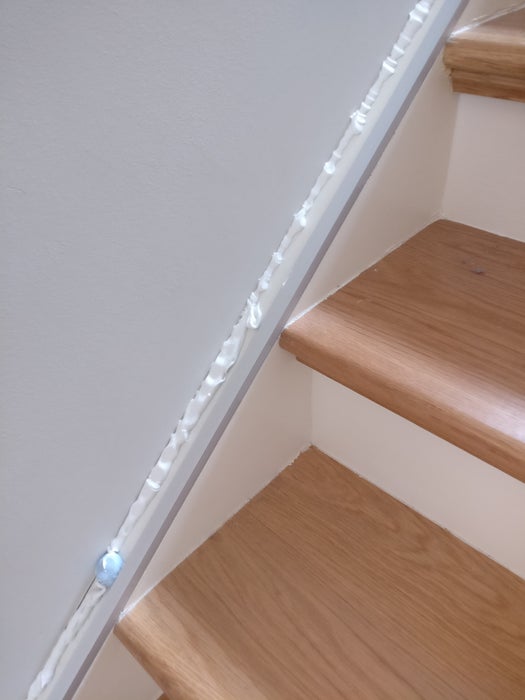
You now need to cover everything with stripwood so it looks embedded into the stairs.
Put as much silicone as you can between the aluminum profiles and the wall. It will serve as a basic brick to lay further silicone when you put the stripwood on top.
Prepare the stripwood by sanding with increasingly finer grain sandpaper. I started with 40 and ended with 120. Paint the stripwood with the same paint of your skirting boards. Let them dry!!!
Give them as many passes as they need. In my case it was 2, to match the job done by the painter on the skirting boards.
Lay the stripwoods on top of the aluminum profiles. You’ll end up with holes. Fill the tiny ones with silicone. For the large ones, cut small pieces of stripwood and repeat the steps above until all holes are filled.
Step 4: Program the Microcontroller
Upload the attached code to the microcontroller. Change your wifi ssid and password so you can upload a new sketch wirelessly via OTA updates.
The program has the following features:
1) it’s parametric in the number of blood drops. Change this line to have more/less drops:
#define DROPS 5
2) it triggers automatically the drops when motion is detected
3) when motion is stopped, it keeps the currently active drops running down. When each drop reaches the bottom, they dissolve, and the lights go off again.
Source: Arduino-based LED “Bloody Red” Automatic Stairs