
Summary of Arduino based Electronic Queuing System
This project describes a DIY Arduino-based queuing system for a clinic, utilizing two custom-built microcontrollers (Sender and Receiver) connected via a CAT5e cable. The Sender accepts patient numbers via a PS2 keyboard and displays them on a mini LCD, while the Receiver triggers a "ding-dong" sound and shows the number on a 32x16 LED dot matrix panel. The design eliminates external crystals by using internal oscillators and avoids expensive USB host shields.
Parts used in the Queuing System:
- ATMEGA328 microcontroller
- PS2 Keyboard
- Matrix keypad (alternative to PS2 keyboard)
- 10K resistor
- 0.1uF capacitor
- 100uF capacitor
- Printed circuit board
- 1602 LCD screen
- 2.2K or 6.8K resistor
- 10K adjustable resistor
- 5V 2A power adapter
- RS232 serial port header (DB9 male and female)
- CAT5e network cable
- 32x16 Dot Matrix LED Display panel
- 470 ohm resistors
- 8021-2 ding-dong doorbell IC
- 2W or 3W amplifier board
- Mini Speaker
- Some wire
This is a Queuing System project requested by a clinic asistant which allows the doctor enter number from a keyboard and display it on a 32×16 LED panel.
This project uses two Arduino, the first Arduino functioned as a SENDER which included a PS2 keyboard and a mini LCD for number input. While the other Arduino is functioned as a RECEIVER which will trigger a “ding-dong” tone and display number on the 32×16 LED panel.
The SENDER uses a PS2 keyboard instead of USB keyboard, USB keyboard will cost higher since it require a USB host shield. You should get a Matrix keypad (please use google translate) in case the PS2 keyboard is not available in the market.
These two Arduino (SENDER & RECEIVER) is connected via a CAT5e network cable, the CAT5e cable provide power to the RECEIVER and also transfer data between two Arduino.
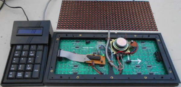
Step 1: What you will learn from this project
- Built your own DIY Arduino without using the Arduino development board
- Using 8MHz internal oscillatior & eliminated the uses of 16 MHz crystal
- Serial communication between two Arduino
- Connect a PS2 keyboard for user input
- Control a Hitachi HD44780 compatible LCD
- Trigger a ding-dong reminder tone
- Driving a 32×16 Dot Matrix Display LED panel
- Monitor serial data while blink the Dot Matrix LED without delay
Step 2: Materials for SENDER
- ATMEGA328 microcontroller
- PS2 Keyboard
- 10K resistor
- 0.1uF capacitor
- 100uF capacitor
- Printed circuit board
- 1602 LCD screen
- 2.2K resistor or resistor 6.8 K
- 5V 2A power adapter
- RS232 serial port header (DB9 male and female each one)
- Some wire
Step 3: Materials for RECEIVER
- ATMEGA328
- Printed circuit board
- 10K resistor
- 0.1uF capacitor
- 100uF capacitor
- 32×16 Dot Matrix LED Display panel
- RS232 serial port header (DB9 male and female each one)
- 470 ohm resistors
- 8021-2 ding-dong doorbell IC
- 2W or 3W amplifier board + Mini SpeakerSome wire
Step 4: Arduino Software Libraries
You must have the following software libraries install on your computer:
Freetronics dot matrix display library: Driving Freetronics 512 pixels (32 × 16 layout) matrix LED display
https://github.com/freetronics/DMD
TimerOne Library: Use with Freetronics dot matrix display library to configure 16bits hardware timer
http://code.google.com/p/arduino-timerone/downloads/list
PS2 Keyboard Library: An Arduino library for PS2 keyboard
http://playground.arduino.cc/Main/PS2Keyboard
LCD Monitor Library: Arduino LiquidCrystal dirver based on the Hitachi HD44780
https://github.com/adafruit/LiquidCrystal
Step 5: Circuit diagrams and source code download
There are two folders (Queue_calling_system_Sender and Queue_calling_system_Receiver) inside the ZIP file, download and extract it to Arduino sketch folder. After that upload the Queue_calling_system_Sender.ino & Queue_calling_system_Receiver to the two Arduino.
Step 6: SENDER PCB design
This is a homemade Arduino (DIY Arduino) , it uses the 8MHZ internal oscillator as the clock source and require very few components. Resistor R3 is used to control the contrast , its resistance can be varies from 2.2K ohms to 6.8K ohms, it is recommended to use an 10K adjustable resistor to test the contrast before selecting a resistor. I have 20 sets mini LCD screen, most of them can use the 2.2K ohm resistor for contrast control, however several of them have to use 6.8K ohm resistor.
R3, LED + and LED- is soldered directly to the PCB in order to reduce the wire connection beween the Arduino & mini LCD screen
Step 7: RECEIVER PCB design
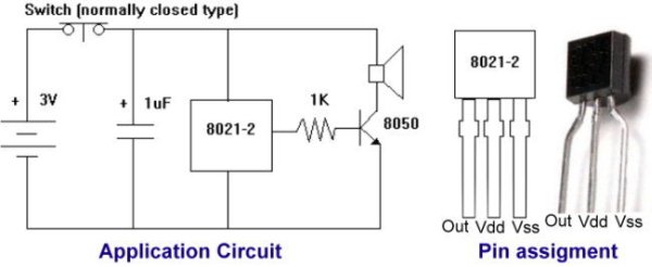
The RECEIVER also using an 8MHZ internal oscillator as the clock source, its design is very similar to SENDER with additional 470 ohm resistor and a 8021-2 ding-dong sound effect IC near to the pin 28 of ATMega328 .
The 8021-2 ding-dong sound effect IC is not able to drive a 3W speaker since its output signal is very weak, and therefore it must connected to a mini-amplifier. I will not talk much about 32×16 Dot Matrix Display panel.
For more detail: Arduino based Electronic Queuing System
-
How does the SENDER unit function?
The SENDER includes a PS2 keyboard and a mini LCD to allow the doctor to enter numbers. -
What is the role of the RECEIVER unit?
The RECEIVER triggers a ding-dong tone and displays the entered number on a 32x16 LED panel. -
Why is a PS2 keyboard used instead of a USB keyboard?
A PS2 keyboard is chosen because a USB keyboard requires a USB host shield which costs higher. -
How are the two Arduinos connected?
The SENDER and RECEIVER are connected via a CAT5e network cable that provides power and transfers data. -
What clock source is used to eliminate the crystal oscillator?
The project uses an 8MHz internal oscillator instead of a 16 MHz crystal. -
Can I use a matrix keypad if a PS2 keyboard is unavailable?
Yes, you should get a Matrix keypad in case the PS2 keyboard is not available in the market. -
Why is an amplifier needed for the speaker?
The 8021-2 ding-dong IC output signal is too weak to drive a 3W speaker directly. -
Which software libraries are required for this project?
You need the Freetronics dot matrix display library, TimerOne Library, PS2 Keyboard Library, and LCD Monitor Library.
