Part 1 – Test Circuit and Test Code
Introduction
Getting your Arduino to transmit via the radio initially may seem daunting but its actually pretty simple. Please freely substitute the word “Arduino” for any micro-controller you wish to use. The example below works for 5V and 3.3V micro-controllers.
Please read this :
This may be the first bit of code you’ve come across with regards to creating a tracker. There is always the temptation to cut and paste it and away you go. And in isolation this may work. However should you then cut and paste further code without understanding what is going you will end up with an unworkable mess and something that is next to impossible for us to assist you with. Pretty please take the time to work out what the code below is doing, redo it yourself, break it, fix it most importantly understand it.
In this short tutorial I’ll give a step by step instructions on connecting a Radiometrix NTX2B to an Arduino and getting it to shift its transmission between two frequencies slightly giving two tones. In the second part I’ll demonstrate how to control this and use the circuit to transmit data at 50 or 300 baud using RTTY. Finally we will demonstrate using the circuit to generate DominoEX.
The theory is as follows: you adjust the voltage on the NTX2B’s TXD pin which adjusts its transmission frequency slightly. The difference in this frequency is called the shift. By doing this in a controlled fashion you can transmit 1’s and 0’s and therefore data. There are a number of methods to adjusting the voltage, connecting the TXD to a PWM (Pulse Width Modulation)on the Arduino, using a DAC or using a voltage divider.
The NTX2B is a FM (Frequency Modulation) module intended to have a voltage applied to the TXD pin of between 0 and 3 volts. This voltage range changes the output frequency of the module by up to 6KHz. This means for each 1Hz change in frequency you need to change the voltage by 0.0005v (3 divided 6000) so to get a shift of 500hz you need to toggle the voltage applied to the TXD pin by 500×0.0005=0.25v.
To get this voltage shift we are going to use PWM . See this article for more information on PWM : [http://arduino.cc/en/Tutorial/PWM|Arduino PWM Tutorial]]. The resolution of this is 8 bits which means the Arduino can change the voltage by 256 (2^8) steps. This means the maximum voltage of 5V can be broken into 5/256 steps or 0.0195v per step. The maximum input of the NTX2B is 3V therefore there is no point applying voltages of greater than 3V. As a decimal this means 3/5* 256 = 153.
In theory the standard shift of 425Hz equates to a 0.2125/0.0195 = 11, however in reality on an NTX2B a value of 10 gave a perfect 425Hz shift. Don’t get too hung up on getting the exact shift, any shift from 350-500Hz is fine.
Items Required
Radiometrix NTX2B
Arduino or similar microcontroller
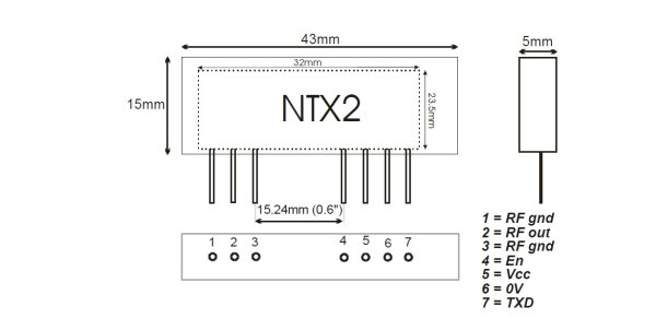
Circuit Diagram
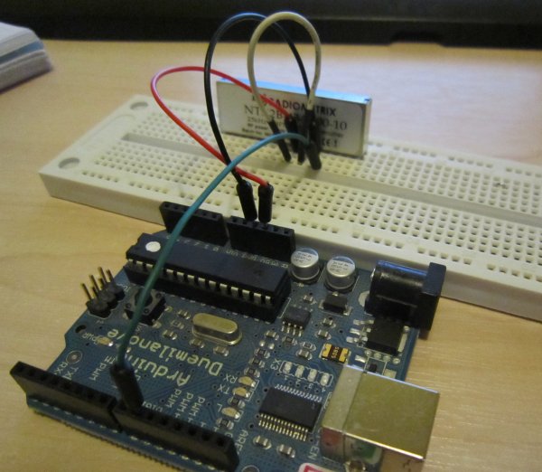
Connect Arduino 5V to the NTX2B VCC pin 5 Connect Arduino 5V to the NTX2B EN pin 4 Connect Arduino GND to the NTX2B GND pin 6 Connect Arduino pin 9 to the NTX2B TXD pin 7
Once done it should look like this (you don’t need an antenna in at this point) :
The Code
The code is similar to the Fade example built into Arduino (File→Examples→03.Analogue→Fade)
/*
 Demo Code to Drive NTX2B via PWM

 Written by Anthony Stirk M0UPU

 This example code is in the public domain.
 */

#define RADIOPIN 9

void setup() {
    pinMode(RADIOPIN, OUTPUT);
    setPwmFrequency(RADIOPIN, 1);
}

void loop() {
    analogWrite(RADIOPIN,100);
    delay(500);
    analogWrite(RADIOPIN,110);
    delay(500);
}
void setPwmFrequency(int pin, int divisor) {
    byte mode;
    if(pin == 5 || pin == 6 || pin == 9 || pin == 10) {
        switch(divisor) {
            case 1:
                mode = 0x01;
                break;
            case 8:
                mode = 0x02;
                break;
            case 64:
                mode = 0x03;
                break;
            case 256:
                mode = 0x04;
                break;
            case 1024:
                mode = 0x05;
                break;
            default:
                return;        }
        if(pin == 5 || pin == 6) {  TCCR0B = TCCR0B & 0b11111000 | mode;}  else {  TCCR1B = TCCR1B & 0b11111000 | mode;  }    }
    else if(pin == 3 || pin == 11) { switch(divisor) {  case 1:    mode = 0x01;   break;
            case 8:
                mode = 0x02;
                break;
            case 32:
                mode = 0x03;
                break;
            case 64:
                mode = 0x04;
                break;
            case 128:
                mode = 0x05;
                break;
            case 256:
                mode = 0x06;
                break;
            case 1024:
                mode = 0x7;
                break;
            default:
                return;        }  TCCR2B = TCCR2B & 0b11111000 | mode;    }}
Excluding the setPwmFrequency procedure (all this does is set the PWM speed as quick as it will go to made the voltage presented to the NTX2B PWM pin as more “analogue”) this code simply opens pin 9. It then alternates the voltage on this pin by 10 every 1/2 second. You can plug an LED into pin 9 to see what its doing.
Load this code up to the Arduino.
Ok now take your radio in USB mode and tune it into the frequency of the NTX2B module. You should hear the high and low tones. If you’re using an RTL + SDR# set the frequency to something above the frequency of the module, i.e in this example our NTX2B is transmitting on 434.200Mhz so I’ve set SDR# to 434.500Mhz. You can see a peak on the left of the spectrum analyzer at the top around 434.200Mhz :
If you’re unsure if this is the radio, turn it off. It will disappear. Zoom in the line using the zoom on the right. You may want to increase the resolution in the FFT Display at this point, with a resolution of 262144 you should see some distinct high and low tones separated by about 425hz :
Part 2 – RTTY
Introduction
Once you have the high and low code working we can now take this one step further and turn this into the transmission of data.
Using the circuit discussed in the previous article upload the following code will transmit a short sentence at 50 baud, 7 bits ASCII 2 stop bits. Also the code adds a CRC checksum at the end of the data string.
The data string variable is passed to a procedure called rtty_txtstring which takes care of transmitting the data by breaking it down into characters, then it transmits the individual bits of those characters. The key to getting the baud rate correct is the timing. Theoretically 50 baud should be 1/50th of a second = 20000µS however the Arduino delayMicroseconds command can only do a maximum delay of 16383µS. To get round this we do two delays of 10000µS.
300 baud after some playing seemed to be stable around 3370µS delay ( 300 baud should be 1/300s = 3333µS). You can uncomment the relevant lines out as needed.
For more detail: Linking an Arduino to a Radiometrix NTX2B Transmitter