Ammeter is used to measure current flow through any load or device. Here in this Arduino Ammeter, we will explain about measuring of current by using ohm’s law. It will be quite interesting as well as a good application of basic science that we studied in our school days.
All of us are well known of ohm’s law, It states that “the potential difference between two poles or terminals of an conductor is directly proportional to the amount of current pass through the same conductor” for constant of proportionality we use resistance, so here it comes the equation of ohm’s law.
V = IR
- V = voltage across the conductor in Volt (v).
- I = current pass through the conductor in Ampere (A).
- R = resistance constant of proportionality in Ohm (Ω).
In order to find the current pass through the device we just rearrange the equation as below, or we can calculate with ohm’s law calculator.
I = V / R
So in order to find out the current, we need some data:
- Voltage
- Resistance
We are going to build a series resistance along with the device. As we need to find voltage drop across the device, for that we need voltage readings before and after the voltage drop, that is possible in the resistance because of no polarity.
Like in the above diagram, we have to find the two voltages that are flowing across the resistor. The difference between the voltages (V1-V2) at the two ends of resistors gives us voltage drop across the resistor (R) and we divide the voltage drop by the resistor value we get the current flow (I) through the device. That is how we can calculate the Current value passing through it, let’s gets into it practical implementation.
Required Components:
- Arduino Uno.
- Resistor 22Ω.
- LCD 16×2.
- LED.
- 10K pot.
- Breadboard.
- Multimeter.
- Jumper cables.
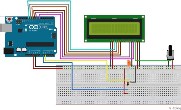
Circuit Diagram and Connections:
The schematic diagram of the Arduino Ammeter Project is follows
The schematic diagram shows the connection of the Arduino Uno with LCD, resistor and LED. Arduino Uno is the power source of the all other components.
The Arduino has analog and digital pins. The sensor circuit is connected to the analog inputs from which we get value of the voltage. The LCD is connect with the digital pins (7,8,9,10,11,12).
The LCD has 16 pins the first two pins (VSS,VDD) and last two pins(Anode, Cathode) are connected to the gnd and 5v. The reset (RS) and enable (E) pins are connected to the Arduino digital pins 7 and 8. The data pins D4-D7 are connected to the digital pins of Arduino (9,10,11,12). The V0 pin is connected to the middle pin of pot. The red and black wires are 5v and gnd.
Current Sensing Circuit:
This Ammeter circuit consists resistor and LED as load. Resistor is connected in series to the LED that current flows through the load and voltage drops is determined from the resistor. The terminal V1, V2 are going to connect with the analog input of the Arduino.
In the ADC of Arduino that coverts the voltage into 10 bit resolution numbers from 0-1023. So we need to covert it in voltage value using the programming. Before that we need to know the minimal voltage that ADC of Arduino can detect, that value is 4.88mV. We multiply the value from ADC with the 4.88mV and we get the actual voltage into the ADC. Learn more about the ADC of Arduino here.
Read more: Arduino Based Digital Ammeter