Summary of Arduino animatronics- make your awesome costumes more awesome
This article guides beginners on building a compact Arduino servo controller board for Halloween costumes and animatronics. It details the assembly process using an Arduino Pro Mini, including soldering surface-mount components like a LiPo charging circuit, USB connector, and various headers. The guide covers tools required, wiring diagrams, code examples, and wireless integration to create interactive projects like animatronic Predators or Iron Man hands.
Parts used in the Arduino Servo Controller Board:
- Soldering iron
- Aoyue 2900 soldering station
- Small tip for SMD components
- Wire cutters/wire strippers
- Tweezers
- Magnifiers
- Multimeter
- Servo board PCB
- Arduino Pro Mini
- USB mini-B connector
- Capacitors (1uF 1210 package)
- Resistor (1K Ohm 1206 package)
- SMD LED (1206 package)
- JST connector
- MAX1555 IC
- Straight break away header pins
- Female break away header pins
- Single cell LiPo battery
- USB mini-B cable
Here’s how to add lights, sound and action to your favorite Halloween project using the open source Arduino microcontroller. Arduino is easy to learn to use and it opens up a whole new world for costume builders and creature creators. If you want to learn how to connect wires, servos, LEDs and use sound effects to add that something special to your latest project then this is for you.
I’ll show you how to make a neat little compact Arduino servo controller board with built in servo connectors that is perfect for costuming and haunted house applications. There are multiple code examples, wiring diagrams and I’ll show you how to connect sensors and even how to connect two controllers using wireless radios.
Here’s a little movie clip of what is easily possible- an animatronic Predator cannon with laser sight, cannon firing sound and head tracking motion control.
Here’s an Iron Man hand repulsor with servo to open the forearm missile compartment. Follow along and find out how to make your awesome costumes more awesome…
Update: My instructable for showing how to make an animatronic Stargate helmet is here-
http://www.instructables.com/id/Animatronic-Stargate-helmet/
Note– While this instructable is written for the beginner, this tutorial assumes you know how to use a soldering iron and other assorted tools like wire strippers and wire cutters. Please be sure to take proper safety precautions, wear safety glasses when using cutting tools and have adequate ventilation when soldering. If you aren’t yet comfortable soldering small surface mount components don’t fret- I’ve posted links in the reference section that will help you become a soldering champ in no time.
Step 1: First you need an Arduino
Arduino? What exactly is Arduino?
Arduino is an open source microcontroller- essentially it is a small computer with an easy to use cross platform programming language. It allows you to create interactive objects based on sensory inputs (physical computing.) You can use it to do something simple like make an LED fade or have a servo move when you push a button or have it do something very complex like control a robot by processing sensor inputs, send the inputs to a computer over a wireless network and then send commands back to the robot. The applications are really limited only by your imagination and there are thousands of examples of cool projects all over the Web. There are several books about Arduino and its capabilities and I’ve listed a few in the reference section.
Which Arduino to use?
There are several variations of the Arduino controller available so which one do you use? It depends on your application. Some have more input pins than others if you need a lot of sensor inputs. For the purposes of this instructable you really can use any Arduino you like as the information presented applies to most every version. Here is a spreadsheet that shows most of the current variations available-
https://spreadsheets.google.com/ccc?key=0AsCUiP6WbJIvcG8xalA3QVdmb3JVT0ptWE9VNC02WEE&hl=en#gid=0
If you are going to use an Arduino Uno or Mega or any Arduino that has built in USB then you can skip to the getting started section.
Building a servo board
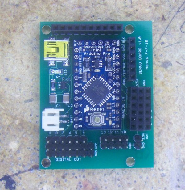
Since my focus is mainly on costume building I decided to use the Sparkfun Arduino Pro Mini and then build a compact servo application board for it that has multiple servo outputs, analog inputs and digital outputs. I also added a socket for an Adafruit Xbee wireless radio adapter as well as a charging circuit for a single cell LiPo battery to power the controller.
The reasons I really like the Pro Mini are its very small form factor, low cost and low power requirements. It operates on 3.3V, which means it can be powered by a single LiPo cell and that makes it easy when connecting sensors that run on 3.3V.
The latest version servo board has eight servo outputs, four digital outputs and six analog inputs. The servo outputs are also digital outputs- they’re just configured to make it really easy to connect hobby servos. The earlier version seen in the photos has six servo outputs. Each servo output has three pins- ground, power and signal. The analog inputs are configured the same way- each input has three pins- ground, power and signal. This configuration makes it super easy to connect individual sensors. The board measures 1.75″ x 2.30″ so it’s pretty small.
The board has a circuit for charging the LiPo cell that powers the controller. There is a mini USB port for 5v input power. Simply connect the battery and then plug in a USB cable and the battery will automatically charge. There is a charging indicator- the LED is on when the battery is charging and then it will automatically turn off when the battery is fully charged.
The mini USB port will also power the controller, even without a battery connected. The mini USB port is only used as a power source connector while charging or during times when a LiPo battery is not available- there is no data transmission using the mini USB port and you are limited by the amount of power a USB port can provide.
Code is uploaded to the controller using a USB to serial adapter (more on this later.) This adapter can also power the controller over USB without the need to connect the battery. This comes in really handy when you’re testing code and you want to power the controller without having to connect the LiPo battery.
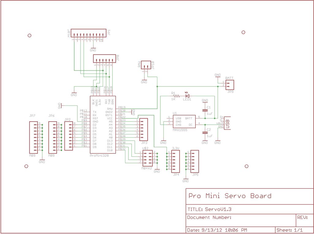
I’m providing all the necessary EAGLE files so people can modify the design to suit their own needs.
EAGLE can be downloaded here- http://www.cadsoftusa.com/
 ServoBoard.zip28 KB
Step 2: Building the controller
Tools and materials
Soldering iron- A good quality soldering iron is a must. I received an Aoyue 2900 soldering station a couple years ago for Christmas and it’s been great. You won’t believe the difference once you start using a good soldering iron. http://sra-solder.com/product.php/6363/22
I also use a small tip for soldering small surface mount components-
http://sra-solder.com/product.php/6397/0
Wire cutters/wire strippers- Small flush cutters are the best. If you don’t have wire strippers or cutters then these will work well-
http://www.adafruit.com/index.php?main_page=product_info&cPath=8&products_id=152
http://www.adafruit.com/index.php?main_page=product_info&cPath=8&products_id=147
Tweezers- Get some small tweezers to work with surface mount components. Here’s an inexpensive set-http://sra-solder.com/product.php/6409/79
Magnifiers- Being able to see what you’re working on makes a world of difference.
http://www.adafruit.com/index.php?main_page=product_info&cPath=8&products_id=291
Multimeter- Most any multimeter will work. You don’t need to spend big $$$. I personally own a Wavetek Meterman 16XL and it’s great. If you don’t already own a multimeter and are really getting into hobby electronics then this meter will probably do everything you could ever want-
http://www.adafruit.com/index.php?main_page=product_info&cPath=8&products_id=308
Servo board PCB-
http://batchpcb.com/index.php/Products/47581
Arduino Pro Mini- http://www.sparkfun.com/products/9220
USB mini-B connector- http://www.sparkfun.com/products/587
capacitors- 2 ea 1210 package 1uF SMD ceramic capacitors
http://us.element-14.com/kemet/c1210x105k5ractu/capacitor-ceramic-1uf-50v-x7r-1210/dp/94M5711
resistor- 1ea 1206 package 1K Ohm SMD resistor
http://us.element-14.com/welwyn/wcr1206-1k0fi/resistor-thick-film-1kohm-250mw/dp/98K2656
LED- 1 ea 1206 package SMD LED
http://us.element-14.com/vcc-visual-communications-company/vaol-s12rp4/led-2×1-5mm-red-133mcd-624nm/dp/27R0088
JST connector- 1 ea
http://www.sparkfun.com/products/8612
MAX1555 IC- 1 ea
http://www.sparkfun.com/products/674
http://us.element-14.com/maxim-integrated-products/max1555ezk-t/ic-battery-charger-li-ion-340ma/dp/59J2761?Ntt=MAX1555
Straight break away header pins – 2ea 40 pin row
These come in really handy so it’s always good to get extras to have on hand
http://www.sparkfun.com/products/116
Female break away header pins- 2 ea 40 hole row
These also are super handy to have around
http://www.sparkfun.com/products/115
Single cell LiPo battery- 1ea (you can use any capacity you like.)
http://www.sparkfun.com/products/339
USB mini-B cable- 1 ea
Odds are you’ve already got one but if you don’t here you go-
http://www.sparkfun.com/products/598
Assembling the servo board
The first thing to do is build the charging circuit. I usually start with the smallest components first. I’ve found the easiest way to solder SMD parts is to get a tiny bit of solder on your soldering tip and touch it to one of the component pads on the PCB. Then hold the component in place using tweezers and heat up the pad and component pin- this allows you to get the part attached to the board so you can check its alignment for the rest of the pads. Then simply solder each of the remaining pads. There is a great series of SMD soldering tutorials here- http://www.sparkfun.com/tutorials/36
Begin by soldering on the MAX1555 IC (labeled U1) -this can only go on one way. Next comes the LED- make sure to check the polarity as it is labeled on the PCB (the LED cathode is connected to one end of R1.) Then solder resistor R1 followed by the capacitors C1 and C2. These can be soldered on either direction. Next comes the mini USB connector- this one is a bit tricky as the pins are positioned nearly underneath the connector. Now solder on the JST connector. Make sure to double check your soldering job for these connectors as they receive a fair bit of mechanical stress.
Now test your charging circuit. Plug in a USB cable and check the voltage at the JST battery connector. It should read about 4.2-4.3V. Now connect the LiPo battery. If everything is OK the small LED should turn on, indicating the battery is charging. Disconnect the battery.
Now solder on the pins to connect the Pro Mini board. This is done by soldering on the break away straight header pins. First insert the long pin ends into the PCB, flip the board over and solder them in place. Double check your solder joints. Now flip the board over and place the Pro Mini board in place on top of the exposed pins and solder all the pins in place. Next solder the remaining straight pins into place in the digital out positions and the 3.3v port along the bottom of the board.
To finish the board solder all the female headers in place. The best way I’ve found to cut the female headers is to remove a pin where you want to make a cut- just yank the pin out the bottom using a pair of pliers. Then take wire cutters and cut through the opening left by the pin. Now take a file (or sandpaper) and smooth out the cut edge.
Make sure your board is getting power by plugging a USB cable into the mini USB port on the controller board. The red LED on the Arduino Pro Mini should light up.
That’s it- your controller is ready to go!
Soldering iron
Magnifiers
Tweezers
For more detail: Arduino animatronics- make your awesome costumes more awesome
- What is Arduino?
Arduino is an open source microcontroller that acts as a small computer with an easy to use cross platform programming language for creating interactive objects. - Which Arduino should I use for this project?
You can use any Arduino version you like, such as the Uno or Mega, as the information presented applies to most every version. - Why did the author choose the Sparkfun Arduino Pro Mini?
The Pro Mini was chosen for its very small form factor, low cost, and low power requirements which allow it to run on 3.3V from a single LiPo cell. - Can the board charge a battery while powered by USB?
Yes, simply connecting the battery and plugging in a USB cable will automatically charge the battery via the built-in charging circuit. - How do you upload code to the controller?
Code is uploaded to the controller using a USB to serial adapter. - Does the mini USB port transmit data?
No, the mini USB port is only used as a power source connector while charging or when a LiPo battery is not available. - What voltage should be read at the JST battery connector during testing?
The voltage should read about 4.2-4.3V when checking the charging circuit with a USB cable plugged in. - How can you verify the board is receiving power?
Plugging a USB cable into the mini USB port should cause the red LED on the Arduino Pro Mini to light up.