In this instructable I’m going to show you how to Interface with LED matrix using an Arduino and MAX7219 IC, this project can be used to make low resolution images using LEDs. This project is very simple to build and serves as a basics to getting started with controlling a large number of LEDs using the Arduino Uno.
For this project we will be using the MAX7219 which is display driver IC, which works with SPI communication. An 8×8 LED matrix has 64 Pins in total if all the cathodes are connected together while an Arudino has only 14 digital pins, and the Arduino is not capable of providing 64 LEDs with enough current so we use the MAX7219, which needs only two Arduino pins to control the LEDS.
Step 1: Tools and Components
Here is the list of components required to build this project, most of these parts can be purchased on eBay –
- Arduino Uno
- 8×8 LED matrix with MAX7219
- Breadboard
- Header Wires
- 5V power supply
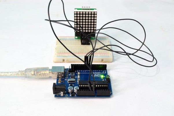
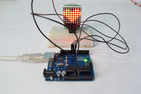
Step 2: Circuit
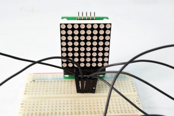
The connections are very simple and can be assembled on a breadboard. The Connections goes as follows –
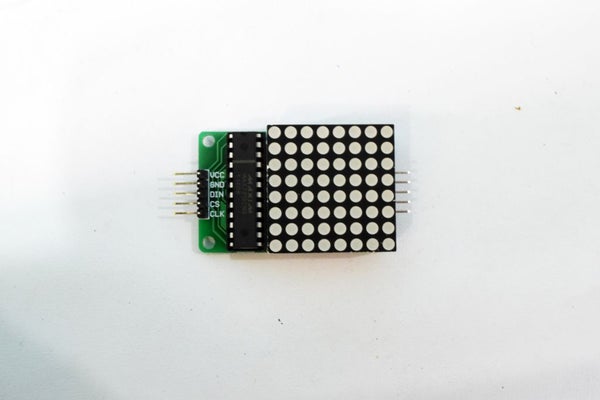
- Max7219 CLK => Arduino digital pin10
- Max7219 CS => Arduino digital pin9
- Max721 DIN => Arduino digital pin8
- Max721 GND => Arduino digital GND
The VCC pin from the LED matrix should be connected to an external 5v power supply (5v 1A recommended), each pin of the Arduino is capable of providing a max current of 40mA. And the 5V regulator is capable of providing a max current of 200mA. The led matrix requires higher operating current.
Step 3: Code
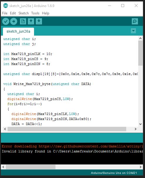
The code can be found below, this is the code to generate a heart shaped object on the LED matrix. The code is simple to understand and you can change the patterns of the LEDs in the code. I will show you how to generate patterns in the next step.
unsigned char i;
unsigned char j;

int Max7219_pinCLK = 10;
int Max7219_pinCS = 9;
int Max7219_pinDIN = 8;

unsigned char disp1[19][8]={0x0c,0x1e,0x3e,0x7c,0x7c,0x3e,0x1e,0x0c};

void Write_Max7219_byte(unsigned char DATA)
{
  unsigned char i;
  digitalWrite(Max7219_pinCS,LOW);
  for(i=8;i>=1;i--)
  {
    digitalWrite(Max7219_pinCLK,LOW);
    digitalWrite(Max7219_pinDIN,DATA&0x80);
    DATA = DATA<<1;
    digitalWrite(Max7219_pinCLK,HIGH);
  }
}

void Write_Max7219(unsigned char address,unsigned char dat)
{
  digitalWrite(Max7219_pinCS,LOW);
  Write_Max7219_byte(address);
  Write_Max7219_byte(dat);
  digitalWrite(Max7219_pinCS,HIGH);
}

void Init_MAX7219(void)
{
  Write_Max7219(0x09, 0x00);
  Write_Max7219(0x0a, 0x03);
  Write_Max7219(0x0b, 0x07);
  Write_Max7219(0x0c, 0x01);
  Write_Max7219(0x0f, 0x00);
}

void setup()
{

  pinMode(Max7219_pinCLK,OUTPUT);
  pinMode(Max7219_pinCS,OUTPUT);
  pinMode(Max7219_pinDIN,OUTPUT);
  delay(50);
  Init_MAX7219();
}

void loop()
{
  for(j=0;j<19;j++)
  {
    for(i=1;i<9;i++)
      Write_Max7219(i,disp1[j][i-1]);
    delay(500);
  }
}
Step 4: Generate Paterns
The patterns are generated by editing an array in the code to the requited hex array, this hex array can be generated by visiting the site below and using the tool to generate hex strings. after you have generated the string you can copy and paste the string in the sample code from the previous step to generate custom patterns.
Source: Arduino 8×8 LED Matrix