
Summary of The Annoy-O-Bug: A Chirping Light-Up Throwie
This article details a compact, affordable prank device called the "Annoy-O-Bug," which fits in a mint tin and emits loud beeps with flashing lights. The project uses an ATtiny85 microcontroller on a custom PCB or breadboard to create an escalating sequence of sounds and visual signals.
Parts used in the Annoy-O-Bug:
- Printed Circuit Board (PCB) from OSH Park
- ATtiny85 Microcontroller (or any compatible microcontroller)
- Buzzer (polarized component)
- LED (polarized component)
- Battery connector
- DIP socket
- Breadboard (optional alternative to PCB)
- Perfboard (optional alternative to PCB)
Small enough to slip in a mint tin, yet loud enough to be heard across a house at only a few dollars per unit. A nice combination for a pretty good prank! Let’s dive in!
Step One: The Circuit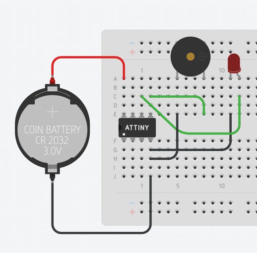
You can purchase the printed circuit board from OSH Park using the link in the parts section of this build. You by no means need to use an ATtiny or my own printed circuit board. This circuit would take a grand total of about 20 minutes to assemble on any breadboard. If you want the circuit to be tiny, however, I would go with the printed circuit board option. If breadboarding it or perfboarding it does interest you, the breadboarded version is shown above. Swap out the ATtiny85 for any microcontroller.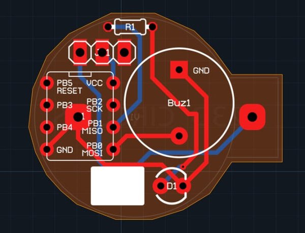
This should be a fairly easy PCB to populate with components. Just keep in mind that the buzzer and LED are polarized components. The buzzer’s longer lead should go through the round pad, and the shorter lead should go through the square pad. The LED’s longer lead should go through hole opposite the white rectangle. The only tricky part of this is getting the battery connector soldered. Make sure you solder all the components on the front first. You can then solder the ground pin of the battery connector to its pad through the hole in the center of the DIP socket.
I have also included a white silkscreen rectangle on the PCB in case you want to write your prankee a small message :). If you would like to customize the PCB, just duplicate my circuits.io design: https://circuits.io/circuits/2677013-annoying-circuit
Step Three: The Software
//Code produced by Alex Wulff: http://www.AlexWulff.com
#define BUZZ      0
#define LED       1
#define INITIAL   5000
//10,000 ms yields a total sequence time of 46.5 Seconds
//20,000 ms yields a total sequence time of 91.5 Seconds
//30,000 ms yields a total sequence time of 136.5 Seconds
//You get the pattern. Each 10 seconds yields another 45
//seconds of total time on the sequence.
void setup() {
 // put your setup code here, to run once:
 pinMode(BUZZ, OUTPUT);
 pinMode(LED, OUTPUT);
 //Flash the light to make sure the device is working
 for (int i = 0; i < 5; i++) {
   digitalWrite(LED, HIGH);
   delay(200);
   digitalWrite(LED, LOW);
   delay(200);
 }
}
void loop() {
 for (int i = 1; i < 50; i++) {
   digitalWrite(BUZZ, HIGH);
   digitalWrite(LED, HIGH);
   delay(30);
   digitalWrite(0, LOW);
   digitalWrite(LED, LOW);
   delay(INITIAL/i);
 }
}
Above is a short sample program that displays some of the capabilities of this device. It is also the program running in the video shown at the top. The time between each subsequent beep gets progressively smaller, which can get really annoying! You could change the time scale on this sketch by changing INITIAL to something much larger. It’s even possible to have this run over the course of a week, getting progressively faster each day!
For more detail: The Annoy-O-Bug: A Chirping Light-Up Throwie
-
Can I build this circuit without the specific PCB?
Yes, you can assemble it on a breadboard or perfboard in about 20 minutes. -
How do I identify the correct orientation for the buzzer?
The longer lead goes through the round pad and the shorter lead through the square pad. -
What is the best way to solder the battery connector?
Solder all front components first, then solder the ground pin of the connector through the hole in the center of the DIP socket. -
Does the LED have a specific placement rule?
Yes, the LED's longer lead must go through the hole opposite the white rectangle. -
How can I change the duration of the prank sequence?
You can change the INITIAL value in the code; increasing it extends the total time significantly. -
Can the device run for more than a few minutes?
Yes, by adjusting the code, it is possible to make the sequence run over the course of a week. -
Is it possible to customize the PCB design?
Yes, you can duplicate the circuits.io design provided in the article to customize the board.
