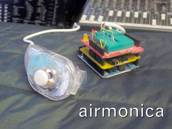
Summary of Airmonica – a free-air musical instrument
The airmonica is a tweakable, easy-to-learn musical instrument that uses a Wii nunchuck as an interface, an Arduino Uno as the controller, and a GinSing shield as the synthesizer to perform harmonic ditties with a tri-tone arpeggiator. It is stackable, expandable, and reuses common prototyping parts; assembly requires minimal modification and connects to speakers via the GinSing output. More details and the project webpage are provided in the instructable.
Parts used in the Airmonica:
- Wii compatible nunchuck (example: NYKO Kama)
- Arduino Uno microcontroller
- GinSing synthesizer shield
- Optional Arduino-compatible prototyping shield (proto board)
- Speaker or stereo system (3.5mm to RCA cable optional)
- Screwdriver and pliers (for nunchuck disassembly)
improvise + harmonize + customize
The airmonica is a easy-to-learn tweakable musical instrument that you can use to perform harmonic musical ditties by accompanying a tri-tone arpeggiator. There are endless opportunities to expand the airmonica in any way that will make it your your own custom instrument. The airmonica consists of three parts:
1. a wii compatible nunchuck as the instrument interface
2. an arduino micro-controller board as the brain
3. a ginsing shield as the synthesizer
In addition to this instructable, you can visit the project webpage at http://www.engeldinger.com/services/latest-project/airmonica
Step 1: Airmonica parts
a stack to hack
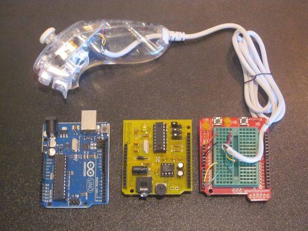
The airmonica consists of 4 basic parts, all of which are easily acquired and require little or no modification. Aside from preparing the nunchuck and installing the software the airmonica can be assembled by just pushing it together. All of the parts in the airmonica can be reused on future projects, and together provide a great prototyping environment for experiments in human interface, computing, and complex waveform synthesis. Here’s what you’ll need:
1. A Wii compatible nunhuck
The nunchuck shown here is an inexpensive 3rd party controller (NYKO Kama). This was chosen because its about half the price of an official Nintendo controller, its clear, has cool flashing lights, and most importantly, can be taken apart with a screwdriver and can put back together later. You can get one for about $10 on Amazon:
2. An Arduino Uno microcontroller ( blue as pictured )
The Arduino Uno is a complete programmable development kit that allows you to run C/C++ code to control is various inputs and outputs. If you don’t have one already you should really get one – its a great way to learn about hardware, software, and embedded applications. It is very affordable and has great support. You can pick one up for about $22 and then download the development environment from the Arduino support page:
3. A GinSing synthesizer shield ( yellow as pictured )
The GinSing is synthesizer board (shield) that plugs onto the Arduino and contains a digital synthesizer chip and an amplifier you plug directly into a speaker (or stereo via 3.5mm jack). For this project the Ginsing is used to create the mellow polyphonic tones you hear produced, but is capable of wide range of sound related applications like synthetic speech, waveform synthesis, and more. The GinSing is available in either kit ($35) or assembled ($45) form from their website:
4. (Optional) proto board ( red & green as pictured )
One thing you may find helpful is an Arduino compatible prototyping shield. In the picture you can see that the nunchuck is connected to the proto board, which not only makes it easier to connect, it also allows you to use the metal pins on nunchuck cable rather than having to cut the cable. If you don’t use you such a board you would just insert the wires into the connector on top of the GinSing board instead (not pictured). The board pictured here is from SparkFun, and an nice because it can be use on other projects that may require switches and LEDs as well:
http://www.sparkfun.com/products/7914
Step 2: Prepare the nunchuck
grip it and rip it ( or snip it or clip it )
To connect the nunchuck to the circuit boards, you will need to expose bare wire or lead pins. In the case of the NYKO Kama controller used here, simply unscrew the connector and slowly pull the wire leads from the connector with pliers, leaving metal tabs that can be inserted into the header pins or proto shield. You can also put the controller back together by reversing the procedure to regain use of the controller at a later time in this case.
Although not used in this project, there are several non-invasive slide-in connectors that expose the contacts of the connector to the circuit board, such as the WiiChuck adapter board available from SparkFun:
http://www.sparkfun.com/products/9281
Step 3: Connect it all together
get to together, man
1. build the shield stack
The Arduino, GinSing, and optional ProtoShield can be stacked on top of each other to connect them. Although you could run wires between the boards, they are designed to seat to each other. Start by placing the GinSing board on top of the Arduino board by aligning the pins on the GinSing to the headers on the Arduino. Note that when placed properly the headphone jack faces way from the USB connector on the Arduino. Depending on your Arduino, you may have extra slots on your headers that have no pins on the GinSing board – this is fine as they are not needed. Be observant when seating the boards together to avoid bent pins; they should fit nicely together but visual alignment is a good precaution.
The ProtoShield can be placed on the GinSing board if you are using one. In the picture below you can see that small wires are used to connect the breadboard rails to the header pins, thus allowing the nunchuck pins to be placed into the corresponding rails. If you are not using a ProtoShield you can skip this step and use the GinSing board header to connect to the nunchuck instead.
2. connect the nunchuck to the stack
The disassembled nunchuck will have either 4 or 5 wires. You need to connect 4 wires, so depending on your controller you may have one you do not need to connect. In the picture below you can see that the Kama nunchuck has 5 wires, but only 4 are connected to the header. Although the color coding of the wires may be different for various controllers. its standard for the power to be red, and the ground to be black, making it easy to find out what the others may be. On the Kama controller, the color coding is:
signal nunchuck header pin
———— ————- —————————————–
power red 5V ( power header – pin 5 )
ground black GND ( power header – pin 6 )
SCL (clock) green A5 ( analog header – pin 6 )
SCA (data) yellow A4 ( analog header – pin 5 )
If you find that your controller does not have this coding, you can experiment with the SCL and SCA lines (analog header pins 5/6) when you are ready; swapping these lines will not damage the airmonica. You may also check the comments on this instructable; it may be possible that others have posted the color coding for the nunchuck you are using.
3. connect to speaker or sound system
The GinSing shield can be connected either directly to a speaker using two contact leads on the board, or through a 3.5 mm stereo jack to either headphones or a stereo system (recommended) using an iPod like connector (typically 3.5mm to RCA ). A thumb wheel on the edge of the board is the volume control. It is recommended to you first set the volume to its lowest setting (fully clockwise) to avoid damaging your ears and bring up the volume once you confirm the airmonica is operating; you’ll see an amber light on the GinSing board glowing as the airmonica starts doing its thing, which is your cue to bring up the volume.
For more detail: Airmonica – a free-air musical instrument
- What is the airmonica?
The airmonica is an easy-to-learn tweakable musical instrument that uses a nunchuck, an Arduino, and a GinSing shield to perform harmonic ditties with a tri-tone arpeggiator. - What parts are required to build the airmonica?
The project uses a Wii compatible nunchuck, an Arduino Uno, a GinSing synthesizer shield, an optional proto shield, a speaker or stereo connection, and basic tools for disassembly. - How do the boards connect together?
The GinSing shield plugs onto the Arduino headers, and the optional proto shield can be stacked on top to route nunchuck connections and wiring. - How is the nunchuck connected to the Arduino?
Disassemble the nunchuck connector to expose wire leads and insert the wires or tabs into the Arduino/GinSing header or proto shield rails matching power, ground, SCL (A5), and SCA (A4). - What are the typical nunchuck wire connections?
Commonly: red to 5V, black to GND, green to SCL (A5), and yellow to SCA (A4); one extra wire may be unused on some controllers. - Can I reuse the parts for other projects?
Yes. All parts can be reused for future projects and provide a prototyping environment for interfaces and synthesis experiments. - How do I connect audio output?
The GinSing can drive a speaker directly via contact leads or connect to headphones/stereo via its 3.5mm jack (use 3.5mm to RCA for stereo systems). - How should I set the volume when first powering up?
Set the GinSing volume to its lowest setting and then increase after confirming operation; an amber light indicates the airmonica is running.