
Summary of A simple Arduino-based tachometer
This article outlines a tutorial for building an Arduino-based tachometer using an IR LED and phototransistor to detect light interruptions. The system calculates RPM intervals and displays results on an LCD, validated using a computer fan with high accuracy.
Parts used in the Arduino-based Tachometer:
- Arduino
- IR LED
- IR Phototransistor
- LCD
- Computer Fan (for validation)
Chris, from PyroElectro.com, proposes a comprehensive tutorial on how to make a simple, yet effective, Arduino-based tachometer.
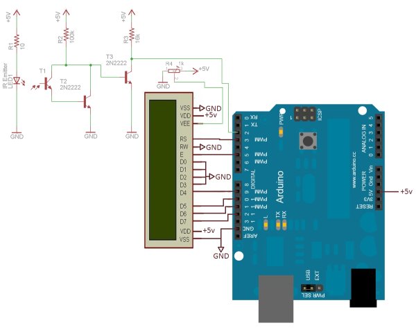
The circuit is very simple: an IR led is coupled with an IR phototransistor to detect possible interruptions of the light beam, while the Arduino is responsible to calculate the time interval between two such events. Finally, a LCD is used to display the current RPM to the user.
To validate his project, a typical computer fan has been used in the set-up and the outcomes have demonstrated to be very close to the true RPM value (2600 +/- 100 RPMs).
The bill of materials, as well as the schematic, the source code and a detailed tutorial on how to build the circuit is available here.
For more detail: A simple Arduino-based tachometer
-
What components are required to build this tachometer?
The project requires an Arduino, an IR LED coupled with an IR phototransistor, and an LCD. -
How does the circuit detect rotation speed?
The circuit detects interruptions of a light beam between the IR LED and the phototransistor. -
What is the role of the Arduino in this setup?
The Arduino calculates the time interval between two detected events to determine the speed. -
How is the RPM value presented to the user?
An LCD is used to display the current RPM calculated by the Arduino. -
Which device was used to validate the project's accuracy?
A typical computer fan was used in the set-up to validate the outcomes. -
What were the test results regarding accuracy?
The outcomes demonstrated values very close to the true RPM, specifically 2600 +/- 100 RPMs. -
Where can I find the schematic and source code?
The bill of materials, schematic, source code, and detailed tutorial are available via the provided link. -
Is this tachometer considered simple or complex?
The article describes the circuit as very simple yet effective.
