In this tutorial we make an LCD shield for using 20 character by four row LCD modules with Arduino Uno.
Updated 18/03/2013
In this article you can follow the process of making another LCD shield for the Arduino Uno or compatible boards. In the past (which explains the word another in this title) I made a 16 x 2 character LCD shield, however it was not backlit, nor large enough. Recently I acquired a 20 x 4 character backlit LCD for use in my Arduino tutorials, therein making this project necessary. To refresh your memories, here is the original shield:
However this time, I cannot mount the display on the shield, it is just too large. Furthermore, it is preferable to be able to stack other shields on top of the new LCD shield. Therefore the display will be external and connected with lengths of wire. So time to get cracking. The first step was to assemble all the parts together. The new LCD has a standard 16-pin HD44780 interface, and is very easy to connect:
What we have: one 20×4 character backlit LCD, a Freetronics basic protoshield, some stacking pin headers, a button, 10k ohm trimpot for contrast adjustment, and some spacers and matching screws to give the LCD some legs. Afterwards I got some 0.1uF ceramic capacitors as well, to smooth supply current on the 5V rail of the shield. Here is the data sheet for the LCD: 2004 LCD.pdf.
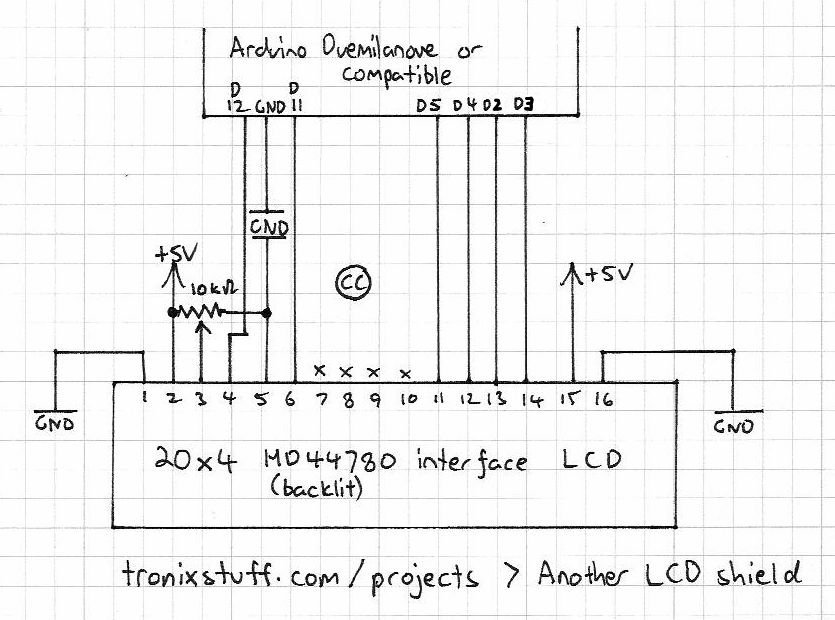
As usual the first thing to do was to make a plan. The LCD interface is easy enough, but I still like to have something on paper to refer to:
The next step is to breadboard it – to make sure it works. However I did solder in the wires to the LCD at this stage:
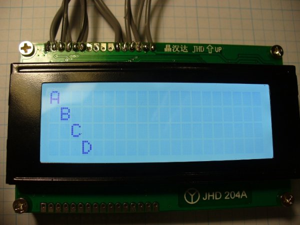
And after assembling the circuit, a brief test:
Project Code and other data:
Success. The demonstration sketch is the example provided with the Arduino IDE, modified for a 20×04 LCD. During the test above, I used an external 5 V power supply for the breadboard. Remember to connect the ground line from the Arduino to the ground line of your breadboard, otherwise it will not work. At this point I was wondering how much current the LCD used by itself. The data sheet claimed it was five milliamps… I think not. Mr Multimeter had a different opinion:
Now it was time to finish the soldering work. Instead of trying to jam all the wires together along the digital pins, I used some wire jumpers to spread out the landing points for the wires from the LCD.
[box color=”#985D00″ bg=”#FFF8CB” font=”verdana” fontsize=”14 ” radius=”20 ” border=”#985D12″ float=”right” head=”Major Components in Project” headbg=”#FFEB70″ headcolor=”#985D00″]Arduino[/box]
For more detail: Make another Arduino LCD shield