In my Arduino 101 tutorial, you’ll be taught how to setup your environment in Tinkercad. I use Tinkercad because it is a pretty powerful online platform that allows me to demonstrate a range of skills to students for building circuits. Feel free to build all my tutorials using the Arduino IDE and a real Arduino!
In this tutorial, we’re going to learn about buttons! We need to know:
- How to wire them up
- Reading their value
- Debounce, and why it’s important
- A practical application (creating a menu)
Most people think the most practical thing to do with a button is turn a light on and off. We’ll, not here! We’re going to use ours to create a menu and set some options on the Arduino.
Ready? Let’s get started!
Step 1: Setup the Board
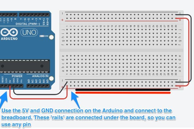
The first step is to put an Arduino and Breadboard Small onto the prototyping area. Check the images above to see how to wire up the power rails.
A Breadboard Mini has two power rails top and bottom. We wire these up to the Arduino so we can provide power to more components. Later in this tutorial we will use 3 buttons so we’ll need more power. The thing to note is that on a breadboard small, the power rails run across the board, horizontally. This is different to the columns in the main prototyping area in the middle; these run vertically. You can use any of the power pins to provide power to any column in the main area in the middle.
When you add power, use black and red wires to the negative and positive respectively. Add wires at the end that run power to the other side of the board. We won’t use that side, but it’s good practise.
Step 2: Add the Button and Resistor
Add a small pushbutton from the components tray. It should look like the one in the image. Make sure it isn’t a switch! Add a resistor, too. Click it, and set its value to 10kΩ. That is enough to pull the pin low when it is not connected, which is very important later in the code.
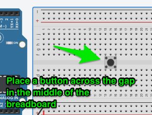
Place the component across the middle of the breadboard. The way a button works is:
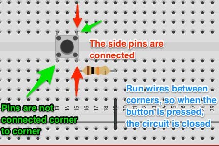
- Corner to corner, the button is not connected. Pushing the button closes the contacts and connects the corners.
- The sides of the button are connected. If you connected a wire to the top left and bottom left, the circuit would be closed.
This is why we put the component across the space in the middle. It makes sure the corners are not connected under the pins in the board.
The next step provides a couple of images that illustrates these points.
Place the resistor from the bottom right pin across columns, so it sits horizontally.
Step 3: Button Connections
The images above make it fairly clear how the buttons connect. It was always a point of confusion when you think something is all good and it doesn’t work!
Now, let’s add the wires.
- Place a red lead from a positive power pin to the same column as the bottom right pin on the button
- Place a black lead from a negative power pin to the same column as the resistor.
- Place a coloured wire (not red/black) from the top left pin to Digital Pin 2 on the Arduino
Check the images above to make sure your wiring is correct.
Step 4: The Code…
Let’s have a look at the code for a basic button.
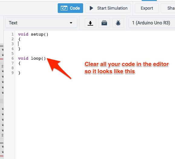
Open the code editor and change from Blocks to Text. Clear the warning that comes up. We’re happy with text!
You know the basic setup, so let’s define the button and do a basic read. We’ll print the output to Serial.
I put a few extra comments into the code below so it’s easier to read than the image.
// Define constants
#define button 2

void setup() {
	pinMode(button, INPUT);
	Serial.begin(9600);
}

void loop() {

	// Read the digital pin to check status of button
	int pressed = digitalRead(button);

	// Button returns HIGH if pressed, LOW if not
	if(pressed == HIGH){
		Serial.println("Pressed!");
	}
}
Ok, well that works!
Essentially, all we’re doing is checking the status of the digital pin each time the code loops. If you click Start Simulation and press the button, you’ll see the Serial Monitor (click the button below the code) display “Pressed!” repeatedly.
One feature you’ll see in the code above is the if() condition evaluation taking place. All the code is doing is asking a question and evaluating if it is true, in this case. We use the is equal (double equal signs, like this: == ) to check if the value of the variable is equal to a certain value. A digitalRead() returns either HIGH or LOW.
Using the if()else if / else we can check many conditions or all conditions, and if you go back to the Arduino Basics, you’ll see some of the comparisons you can make.
Now… Our code might look complete… But we have a problem.
See, that works really well when in the simulator. But real electricity has noise, especially DC electronics. So our button might return a false reading sometimes. And that’s a problem, because your project might not respond the right way for the user.
Let’s fix it!
Step 5: A Little Debounce
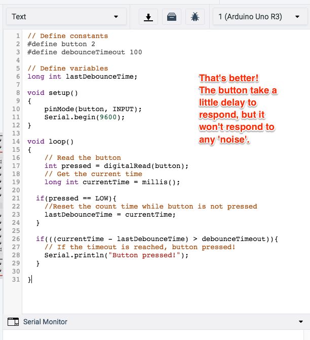
We use a procedure called debounce to overcome our button problem. This essentially waits a specified amount of time between when the button was pushed and actually responding to the push. It still feels natural to the user (unless you make the time too long). You can also use it for checking length of press, so you can respond differently each time. You don’t need to change any of the wiring!
Let’s look at the code:
#define button 2<br>#define debounceTimeout 100
The first change is on the global scope. You’ll remember that’s where we define variables lots of our functions might use or those that can’t be reset each time the loop fires. So, we added debounceTimeout to the defined constants. We made this 100 (which will later translate to 100ms), but it could be shorter. Any longer and it’ll feel unnatural.
long int lastDebounceTime;
This variable is declared below the constants. This is a long int type, which basically allows us to store long numbers in memory. We called it lastDebounceTime.
We don’t need to change anything in the void setup() function. Let’s leave that one.
void loop() {<br>	// Read the digital pin to check status of button
	int pressed = digitalRead(button);
	long int currentTime = millis();

	// Button code
}
The first change we make in the loop() function is under the call to read the button. We need to keep track of the current time. The millis() function returns the current time of the clock since the Arduino booted up in milliseconds. We need to store this in a long int type variable.
Now, we need to make sure we are aware of the time since the button was pressed, so we reset the timer when it isn’t pressed. Take a look:
void loop() {<br>	// Read the digital pin to check status of button
	int pressed = digitalRead(button);
	long int currentTime = millis();

	if(pressed == LOW){
		// Reset the count time while button is not pressed
		lastDebounceTime = currentTime;
	}

	// Button code
}
The if(pressed == LOW) algorithm checks if the button isn’t pressed. If it isn’t, then the code stores the current time since last debounce. That way, each time the button is pressed, we have a point in time from which we can check when the button was pressed. We can then do a quick mathematical calculation to see how long the button was pressed for, and respond correctly. Let’s look at the rest of the code:
void loop() {<br>	// Read the digital pin to check status of button
	int pressed = digitalRead(button);
	long int currentTime = millis();

	if(pressed == LOW){
		// Reset the count time while button is not pressed
		lastDebounceTime = currentTime;
	}
	// Button has been pressed for a given time
	if(((currentTime - lastDebounceTime) > debounceTimeout)){
		// If the timeout is reached, button pressed!
		Serial.println("Pressed!");
	}
}
The last block of code takes the current time, subtracts the last debounce time and compares it to the timeout we set. If it is greater, the code assumes the button has been pressed for that time and responds. Neat!
Run your code and check it works. If you have errors, check your code!
Now, let’s look at a practical example.
Step 6: The Making of a Menu
Buttons are interesting, because there are so many possibilities with them! In this example, we’re going to make a menu. Let’s say you’ve created this really great device, and need users to be able to change options to turn certain things on or off, or set a particular value for a setting. This three button design can do that!
So, for this project we need:
- Three buttons
- Three resistors set to 10kΩ
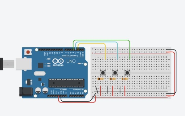
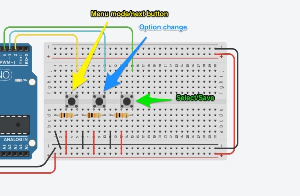
We already have one of these, we just need the other two. So add those to the board. Wiring up is a little more complex, but only because I wanted to keep it really compact. You could follow the same pattern for the first button, or follow the image above.
The three buttons are a menu open/next option, a change option (as in, alter the setting), and a save/close menu button.
Wire it up, let’s look at the code!
Step 7: Code Breakdown – Global
Ok, this is going to be a long step, but I am going to go through each section of code.
First, let’s look at the global variables needed.
// Define constants<br>#define menuButton 2
#define menuSelect 3<br>#define menuSave 4
#define debounceTimeout 50
<br>// Define variables
int menuButtonPreviousState = LOW;
int menuSelectPreviousState = LOW;
int menuSavePreviousState = LOW;
long int lastDebounceTime;
<br>// Menu options
char * menuOptions[] = {"Check Temp", "Check Light"};
bool featureSetting[] = {false,false};
bool menuMode = false;
bool menuNeedsPrint = false;
int optionSelected = 0;
These three blocks are fairly similar to what we have seen before. In the first, I have defined the three buttons and the timeout. For this part of the project, I have set it to 50ms so it takes a deliberate press to make it work.
The second block is all the variables. We need to keep track of the buttonPreviousState, and we need to keep track of the lastDebounceTime. These are all int type variables, but the last is a long type because I am assuming we need the space in memory.
The menu options block has a few new features. First, the char * (yes, that is a deliberate asterisk), which is a character/string literal variable. It is a pointer to a static storage in memory. You can’t change it (like you can in Python, for example). This char *menuOptions[ ] line creates an array of string literals. You could add as many menu items as you like.
The bool featureSetting variable is just the array of values that represents each menu item. Yes, you could store anything you like, just change the variable type (they all have to be the same type). Now, there might be better ways to manage this, like dictionaries or tuples, but this is simple for this application. I would probably create one of the latter in a deployed application.
I have kept track of the menuMode, so if I wanted other things on my display I could do that. Also, if I had sensor logic I might pause that during menu operation, just in case something conflicts. I have a menuNeedsPrint variable because I want to print the menu at specific times, not just all the time. Finally, I have an optionSelected variable, so I can keep track of the option selected as I access it in a number of places.
Let’s look at the next set of functions.
Step 8: Code Breakdown – Setup and Custom Functions
The setup() function is easy enough, just three input declarations:
void setup() {<br>	pinMode(menuSelect, INPUT);
	pinMode(menuSave, INPUT);
	pinMode(menuSelect, INPUT);
	Serial.begin(9600);
}
Next are the three custom functions. Let’s look at the first two, then the last one separately.
We need two functions that return some information. The reason is, we want to make sure this is sort of human readable. It will also help with debugging the code if we have an issue. Code:
// Function to return the current selected option<br>char *ReturnOptionSelected(){
	char *menuOption = menuOptions[optionSelected];
	// Return optionSelected
	return menuOption;
}
// Function to return status of current selected option
char *ReturnOptionStatus(){
	bool optionSetting = featureSetting[optionSelected];
	char *optionSettingVal;
	if (optionSetting == false){
		optionSettingVal = "False";
	}else{
		optionSettingVal = "True";
	}
	// Return optionSetting
	return optionSettingVal;
}
The char *ReturnOptionSelected() function checks the option selected (if you see above, we set a variable to keep track of that), and pulls the string literal from the array we created earlier. It then returns it as a char type. We know this because the function indicates the return type.
The second function, char *ReturnOptionStatus() reads the status of the option saved in the array and returns a string literal that represents the value. For example, if the setting we have stored is false, I would return “False”. This is because we show the user this variable and it is better to keep all this logic together. I could do it later, but it makes more sense to do it here.
// Function to toggle current option<br>bool ToggleOptionSelected(){
	featureSetting[optionSelected] = !featureSetting[optionSelected];
	return true;
}
The function bool ToggleOptionSelected() is a convenience function to change the value of the setting we have selected in the menu. It just flips the value. If you had a more complex set of options, this might be quite different. I return true in this function, because my callback (the call later in the code that fires this function) expects a true/false reply. I am 100% sure this will work, so I didn’t account for it not working, but I would in a deployed application (just in case).
Source: A Menu in Arduino, and How to Use Buttons